Transmitting device, receiving device, transmitting method, and receiving method
a technology of transmitting device and receiving device, which is applied in the direction of transmission path sub-channel allocation, wireless communication, wireless commuication services, etc., can solve the problems of inability to assign downlink data to the terminal, decrease in system throughput, and shorten the resources of the system, so as to reduce the inequalities of the reception characteristics of control information
- Summary
- Abstract
- Description
- Claims
- Application Information
AI Technical Summary
Benefits of technology
Problems solved by technology
Method used
Image
Examples
embodiment 1
[Communication System Overview]
[0055]A communication system according to the present embodiment includes a transmission apparatus and a reception apparatus. In particular, the present embodiment is described by taking base station 100 as the transmission apparatus and taking terminal 200 as the reception apparatus. The communication system is, for example, an LTE-Advanced system. Base station 100 is, for example, a base station that supports the LTE-Advanced system, and terminal 200 is, for example, a terminal that supports the LTE-Advanced system.
[0056]FIG. 5 is a block diagram illustrating main components of base station 100 according to the present embodiment.
[0057]In base station 100, search space configuration section 102 configures search spaces formed by a plurality of “mapping candidates” based on aggregation level values. Each mapping candidate is formed of the same number of CCEs (control channel elements) as the aggregation level value. The CCEs are obtained by dividing e...
configuration example 1
[0114]FIG. 9 illustrates an example of configuring search spaces according to configuration example 1. The search spaces shown in FIG. 9 are configured for a single terminal 200, and search spaces different from the search spaces shown in FIG. 9 are configured for terminals 200 other than terminal 200 corresponding to FIG. 9.
[0115]As shown in FIG. 9, for aggregation level 1, CCE 0, CCE 5, CCE 10 and CCE 15 are configured as one mapping candidate. That is, for aggregation level 1, CCE #(4N), CCE #(4N+1), CCE #(4N+2) and CCE #(4N+3) are each configured as a single mapping candidate.
[0116]Further, as shown in FIG. 9, for aggregation level 2, a pair of CCE 1 and CCE 3, a pair of CCE 4 and CCE 14, a pair of CCE 9 and CCE 3, and a pair of CCE 12 and CCE 14 are each configured as a single mapping candidate. That is, for aggregation level 2, a pair of CCE #(4N) and CCE #(4N+2) or a pair of CCE #(4N+1) and CCE #(4N+3) is configured as one mapping candidate.
[0117]Further, as shown in FIG. 9, ...
configuration example 2
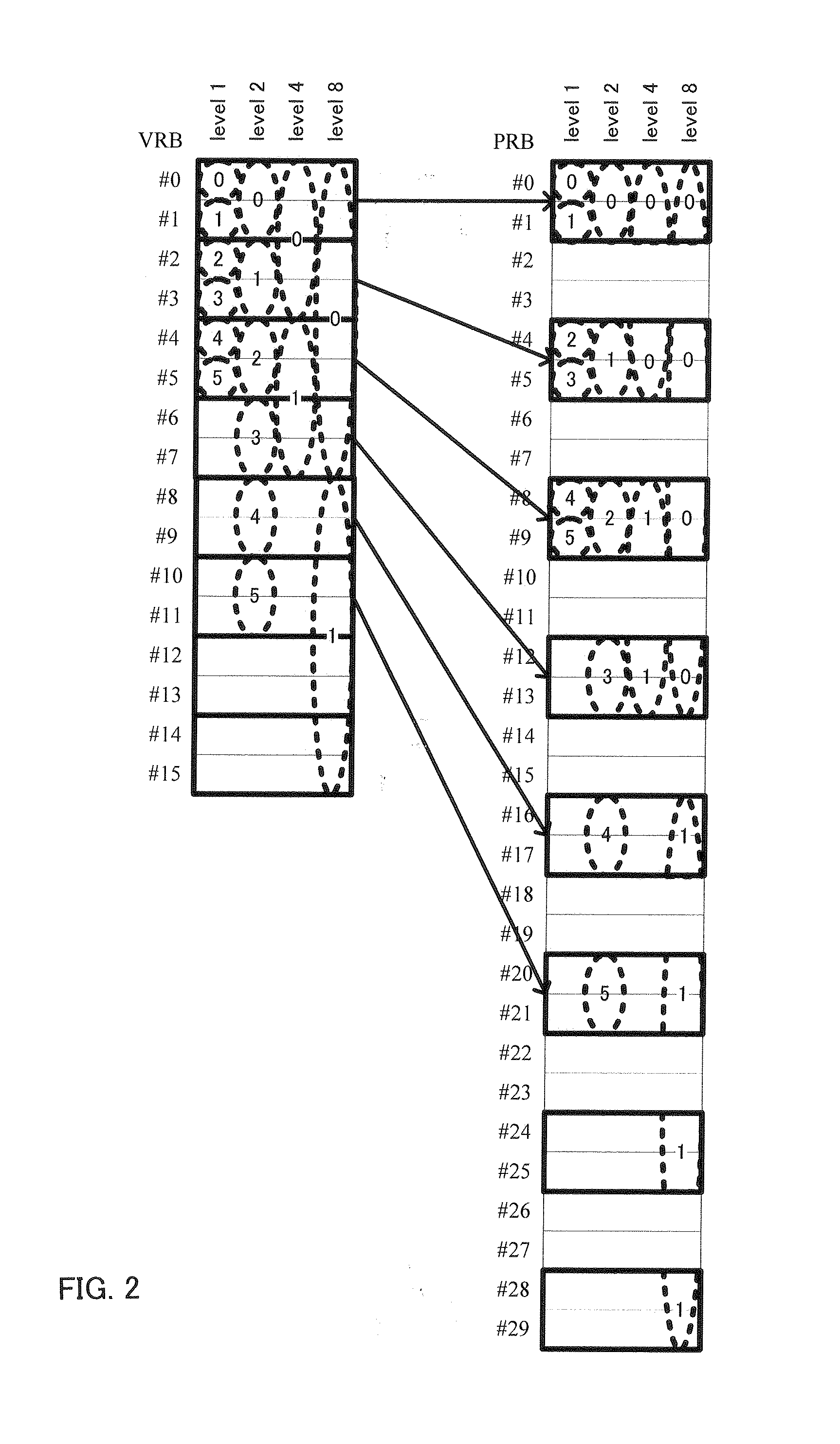
[0119]“Localized allocation” which allocates ePDCCHs collectively at positions close to each other on the frequency band, and “distributed allocation” which allocates ePDCCHs by distributing the ePDCCHs on the frequency band are being studied as allocation methods for ePDCCHs (for example, see FIG. 10). Localized allocation is an allocation method for obtaining a frequency scheduling gain, and can be used to allocate ePDCCHs to resources that have favorable channel quality based on channel quality information. Distributed allocation distributes ePDCCHs on the frequency axis, and can obtain a frequency diversity gain. In the LTE-Advanced system, both a search space for localized allocation and a search space for distributed allocation may be configured (for example, see FIG. 10).
[0120]Therefore, according to configuration example 2, a case is described in which a search space for localized allocation is configured for aggregation level 2 (aggregation level 1), search spaces for both ...
PUM
 Abstract
Description
Claims
Application Information
 - R&D
- Intellectual Property
- Life Sciences
- Materials
- Tech Scout
- Unparalleled Data Quality
- Higher Quality Content
- 60% Fewer Hallucinations
Browse by: Latest US Patents, China's latest patents, Technical Efficacy Thesaurus, Application Domain, Technology Topic, Popular Technical Reports.
© 2025 PatSnap. All rights reserved.Legal|Privacy policy|Modern Slavery Act Transparency Statement|Sitemap|About US| Contact US: help@patsnap.com


