Method of scrambling signals, transmission point device and user equipment using the method

a signal and transmission point technology, applied in the field of signal multiplexing method and reference signal design in communication system, can solve the problems of interference between dmrss from adjacent transmission points and dmrss from multiple transmission points, and achieve the effect of reducing signal overhead

Active Publication Date: 2014-03-13
SUN PATENT TRUST
View PDF8 Cites 66 Cited by
  • Summary
  • Abstract
  • Description
  • Claims
  • Application Information

AI Technical Summary

Benefits of technology

[0026]In the present disclosure, by generating random seeds for initializing scrambling sequences for DMRSs based on UE specific IDs or group IDs, identical DMRS from multiple transmission points are guaranteed for the JT scenarios while different DMRSs from adjacent transmission points are guaranteed for the non-CoMP scenarios. Further, by switching between release-10 DMRS random seeds and UE specific DMRS random see

Problems solved by technology

Therefore, for the JT operation, in order to correctly combine signals from the multiple transmission points, identical DMRS from the multiple transmission points are necessary; otherwise, DMRS from the multiple transmission points can

Method used


Image

  • Method of scrambling signals, transmission point device and user equipment using the method
  • Method of scrambling signals, transmission point device and user equipment using the method
  • Method of scrambling signals, transmission point device and user equipment using the method

Examples


first embodiment

[0054]FIG. 7 is a block diagram showing a transmission point device according to the first embodiment of the present disclosure.

[0055]The transmission point device 700 according to the first embodiment of the present disclosure is used for communicating with a UE in a communication system. The transmission point device 700 transmits, to the UE, RS signals which are assigned on predetermined locations (radio resource, which means the time and / or frequency resource such as sub-carrier, sub-frame, etc.) of at least one layer of resource blocks with the same time and frequency resources. As shown in FIG. 7, the transmission point device 700 may include a random seed generation unit 701, an initialization unit 702, a scrambling unit 703, and a transceiver unit 704. The random seed generation unit 701 generates a random seed based on a UE specific ID. The initialization unit 702 initializes a scrambling sequence by the random seed generated in the random seed generation unit 701. The scra...

second embodiment

[0067]Comparing the equation (2) brought forward in the first embodiment and the equation (1) for DMRS random seed generation in release-10, it is found that the random seeds generated from the equation (2) may collide with the random seeds generated from the equation (1), because the range of the parameter n_RNTI in the equation (2) is 0˜216−1. Considering a case where the random seeds generated from the equation (1) are assigned for release-10 UEs while the random seeds generated from the equation (2) are assigned for release-11 UEs, Such collision may produce problems if release-10 UEs with the random seeds generated from the equation (1) and release-11 UEs with the random seeds generated from the equation (2) coexist.

[0068]To resolve the above collision problem, equation (3) gives one exemplary improvement on the equation (2) in the first embodiment as follows

cinit=(└ns / 2┘+1)·(2*Max+1)·216+(n_RNTI+2)  (3)

Where Max=Maxim_value(cell_id), representing the maximum value of transmiss...

third embodiment

[0071]As described before, the blind detection of DMRS at a receiver side can help an UE to estimate the interference in MU-MIMO operation. However, if the equation (2) or (3) is used to generate DMRS random seeds, the UE may not be able to perform the blind detection, because there are too many possibilities for the UE specific random seeds or the blind detection space is too large in this case. For example, since there are 216 possibilities for the value of n_RNTI in both the equation (2) and the equation (3) as discussed above, there are 216 possibilities for random seeds generated from the equation (2) or (3), which results in much more dimensions of DMRS than those of FIG. 6 using the release-10 DMRS random seed generation equation (1). It is difficult to perform the blind detection of DMRS in a case of too many dimensions of DMRS.

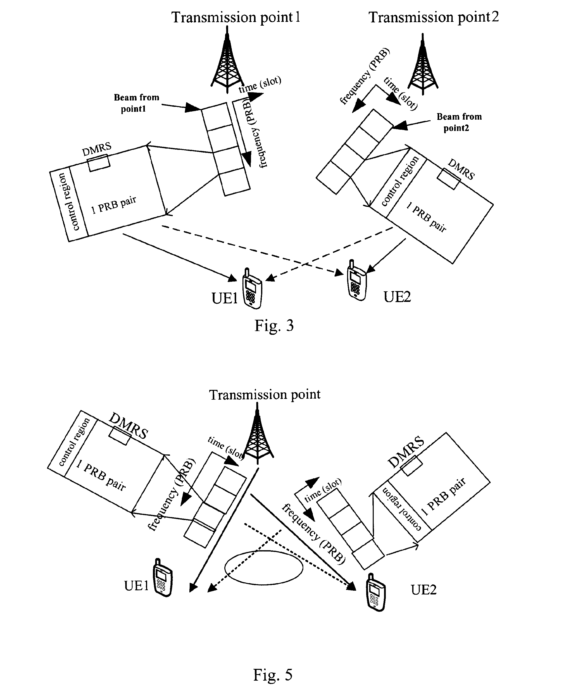
[0072]Orthogonality between MU-MIMO DMRS ports is another concern for the equation (2) and the equation (3). As shown in FIG. 5, there are two UEs, i...


PUM


Abstract

Method of scrambling signals, transmission point device and user equipment using the method are provided. The method is for scrambling signals assigned on predetermined radio resources of at least one layer of resource blocks with the same time and frequency resources, and comprises the steps of: sending an ID table to a user equipment through higher layer signaling, the ID table being a subset of the whole ID space and containing available IDs for the user equipment; notifying the user equipment an ID in the ID table to be used through physical layer signaling or UE specific higher layer signaling; generating a random seed based on the notified ID; initializing a scrambling sequence by the random seed; and scrambling the signals with the initialized scrambling sequence. The method of the disclosure, by combining physical layer signaling and higher layer signaling, may notify the used group ID and the blind detection space to a UE, the blind detection for the UE is enabled and the signaling overhead is reduced.

Description

TECHNICAL FIELD[0001]The present disclosure relates to the field of signals multiplexing method and reference signal design in communication system.BACKGROUND[0002]DMRS (Demodulation Reference Signal) or UE (User Equipment) specific reference signal is one of RS (Reference Signals) used in LTE-A (Long-Term Evolution-Advanced) (release-10, release-11, etc). DMRS is the same precoded as the data part in a LTE-A system, so it can provide the channel estimation for demodulation.[0003]FIG. 1 is a schematic diagram showing an example of DMRS multiplexed. FIG. 1 shows a structure of RB (resource block) and DMRS. In FIG. 1, there is shown one RB. The abscissa axis (T) of the RB represents time (OFDM symbols), and its vertical axis (F) represents width of frequency band (sub-carriers). For the RB, the abscissa axis is divided into 14 sections, each of which forms an OFDM symbol in the vertical axis direction. The vertical axis is divided into 12 sections, each of which forms a sub-carrier in...

Claims


Application Information

Patent Timeline
IPC IPC(8): H04L5/00
CPCH04L5/0016H04L25/0226H04L5/0051H04L27/2613H04L27/26H04W72/044H04W72/121
Inventor ZHANG, ZHIXU, MINGHOSHINO, MASAYUKIIMAMURA, DAICHINISHIO, AKIHIKO
Owner SUN PATENT TRUST
Why Eureka
Try Eureka