Software configurable distributed antenna system and method for reducing uplink noise

Active Publication Date: 2014-03-13
DALI WIRELESS
View PDF1 Cites 176 Cited by
  • Summary
  • Abstract
  • Description
  • Claims
  • Application Information

AI Technical Summary

Benefits of technology

[0012]The embodiments of the present invention described herein provide additional features that enhance the cost-effectiveness, flexibility and system performance of conventional systems with multiple remote antenna units in comparison with conventional techniques and systems. Embodiments of the present invention are applicable to a variety of communications products including the Digital Access Unit (DAU) and Remote Radio Head Unit (RRU).
[0015]The present invention exploits the reconfigurability features of the RRU to route and switch a specific group of uplink data packets associated with a specific group of RRUs so they are directed to the appropriate DAU. These uplink data packets correspond to a particular uplink RF frequency band. The present invention also exploits the reconfigurability features of the DAU to route a specific group of uplink data packets associated with a specific group of RRUs, then performs appropriate signal processing and filtering functions and provides a combined RF signal representing the appropriate RRU data packets and in turn routes the combined RF signal to the appropriate RF uplink port of the DAU. As a result of applying the correct data packet routing and switching, signal processing and filtering, the uplink noise associated with a specific group of RRUs is significantly reduced [this section needs editing, based on the detailed description of invention].
[0016]An embodiment of the present invention utilizes one or more RRUs. The objective of the RRU is to (on the Downlink path) accept an optical serial data stream coming in via an optical fiber link, process it and convert it to RF signals, amplify those signals and deliver them to the antenna. The objective of the RRU is to (on the Uplink path) receive RF signals from the antenna(s), convert and process them into a serial data stream, and deliver the serial data stream to the DAU via the optical fiber link. An embodiment of the present invention utilizes one or more DAUs. The objective of the DAU is to (on the Downlink path) accept RF signals from base station sectors, convert and process the signals into a serial data stream, and deliver the serial data stratum to RRUs via optical fiber links. The objective of the DAU (on the Uplink path) is to receive optical serial data streams, process and convert those data streams to RF signals, and deliver the RF signals to specific base station sectors. The DAS comprised of one or more DAUs and multiple RRUs can be dynamically configured to reduce the uplink noise as voice and data traffic loading changes at the RRUs.
[0018]The present invention is also field upgradeable and / or remotely reconfigurable through a link such as an Ethernet connection to a remote operations and monitoring center. This feature adds to the present invention's flexibility and cost-effectiveness.
[0019]The present invention provides enhanced uplink system performance, however it does not require the use of multiple uplink antennas for a given frequency range at each RRU and does not have a negative impact on optical fiber link capacity and / or optical fiber link cost.
[0020]Numerous benefits are achieved by way of the present invention over conventional techniques. For example, embodiments of the present invention enhance system throughput and quality of service in comparison with conventional systems. Additionally, embodiments of the present invention reduce the system noise and enhance the system capacity. These and other embodiments of the invention along with many of its advantages and features are described in more detail in conjunction with the text below and attached figures.

Problems solved by technology

Wireless and mobile network operators face the continuing challenge of building networks that effectively manage high data-traffic growth rates.

Method used


Image

  • Software configurable distributed antenna system and method for reducing uplink noise
  • Software configurable distributed antenna system and method for reducing uplink noise
  • Software configurable distributed antenna system and method for reducing uplink noise

Examples


Embodiment Construction

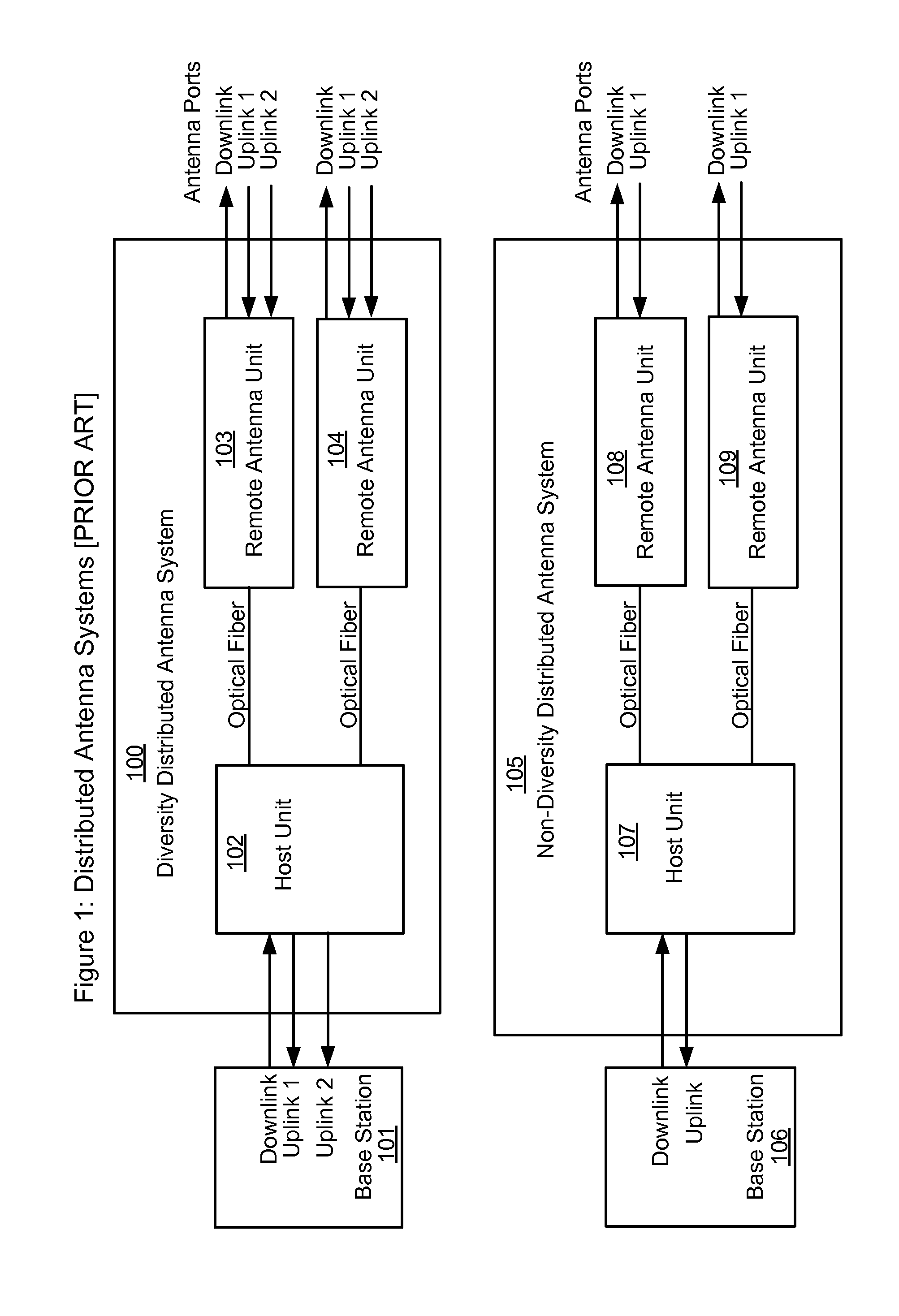
[0035]A DAS may be configured to employ uplink diversity, where each remote antenna unit supports two uplink receive antennas. In such a case, two separate uplink signal paths are provided from each remote antenna unit to the host unit and onward to the base station uplink receive antenna ports. A DAS that has two receive antennas deployed at each remote antenna unit location may provide enhanced system performance. However, the additional physical space and costs associated with providing uplink diversity antennas and diversity signal processing at the remote antenna units may not be practical for some outdoor and indoor DAS deployments. Some DAS solutions require deployment of a separate optical fiber per remote antenna unit to support uplink diversity, which may further increase capital and operational costs. For some digital-over-fiber systems, the need to provide a second uplink path dramatically increases the required upstream data transport rate. The required upstream data tr...


PUM


Abstract

A distributed antenna system includes a master unit including a downlink RF input operable to receive an RF input signal from a downlink port of a base station, a first optical port, and a second optical port. The distributed antenna system also includes a first remote unit coupled to the first optical port. The first remote unit comprises a downlink antenna port and a first uplink antenna port and a second remote unit coupled to the second optical port of the master unit. The second remote unit comprises a downlink antenna port and a second uplink antenna port. The master unit is operable to transmit a first RF signal associated with the first RF uplink signal to a first uplink port of the base station and transmit a second RF signal associated with the second RF uplink signal to a second uplink port of the base station.

Description

CROSS-REFERENCES TO RELATED APPLICATIONS[0001]This application claims priority to U.S. Provisional Patent Application No. 61 / 530,888, filed on Sep. 2, 2012, entitled “Software Configurable Distributed Antenna System and Method for Reducing Uplink Noise,” the disclosure of which is hereby incorporated by reference in its entirety for all purposes.BACKGROUND OF THE INVENTION[0002]Wireless and mobile network operators face the continuing challenge of building networks that effectively manage high data-traffic growth rates. Wireless and mobile technology standards are evolving towards higher bandwidth requirements for both peak rates and cell throughput growth.[0003]Conventional radio base stations employed in wireless networks which utilize various 2G, 3G and 4G radio technologies (such as CDMA, 1XEV-DO, WCDMA, WiMAX-SISO, LTE-SISO, etc.) routinely include an Uplink Diversity feature. Wireless base stations have been equipped for Uplink Diversity for more than 20 years.[0004]When a bas...

Claims


Application Information

Patent Timeline
Patent Type & Authority Applications(United States)
IPC IPC(8): H04B7/04H04B17/40
CPCH04B7/04H04W88/085H04B7/022H04B10/25753
Inventor LEMSON, PAULSTAPLETON, SHAWN PATRICKTRAJKOVIC, SASA
Owner DALI WIRELESS
Why Eureka
Try Eureka