
Software configurable distributed antenna system and method for bandwidth compression and transport of signals in noncontiguous frequency blocks

a distributed antenna and bandwidth compression technology, applied in the direction of wireless communication services, electrical equipment, wireless commuication services, etc., can solve the problems of reducing the effective optical data rate, affecting the cost and performance of the system, and inefficient use of the optical data rate, so as to reduce the total bandwidth needed, reduce the optical data transport rate, and improve the effect of performan

Active Publication Date: 2014-01-09
DALI SYST LTD
View PDF0 Cites 27 Cited by
  • Summary
  • Abstract
  • Description
  • Claims
  • Application Information

AI Technical Summary

Benefits of technology

The patent describes a system for efficiently transporting signals between a base station and multiple remote antenna units. This is achieved through the use of digital remote units and digital access units, which may be connected through optical fiber, coaxial cable, or other transport media. The system also includes signal processing techniques to reduce the data rate associated with transport of the signals, which improves cost-effectiveness, flexibility, and system performance. Overall, the patent provides a solution for applications where multiple remote antenna units are needed.

Problems solved by technology

In the case of an optical fiber transport medium, the transport data rate is a critical parameter that affects the cost and performance of the system.
However, this would be a very inefficient use of the optical transport data rate.
Although this approach would reduce the effective optical transport data rate, the addition of the channelized filters increases the system delay and complexity.

Method used


Image

  • Software configurable distributed antenna system and method for bandwidth compression and transport of signals in noncontiguous frequency blocks
  • Software configurable distributed antenna system and method for bandwidth compression and transport of signals in noncontiguous frequency blocks
  • Software configurable distributed antenna system and method for bandwidth compression and transport of signals in noncontiguous frequency blocks

Examples


Embodiment Construction

[0032]According to embodiments of the present invention, a novel Distributed Antenna System (DAS) that exploits the Software Configurable Radio subsystem (referred to hereinafter as software defined radios or a software-defined digital platform) is provided. Embodiments enable DAUs, RRUs, and DRUs to communicate with each other.

[0033]Moreover, the system is flexible with regard to being able to support various radio technologies, such as CDMA, CDMA 1xEV-DO, TD-SCDMA, WCDMA and LTE. However, embodiments may not be limited to these, as other applicable radio technologies may be apparent to those with ordinary skill in the art.

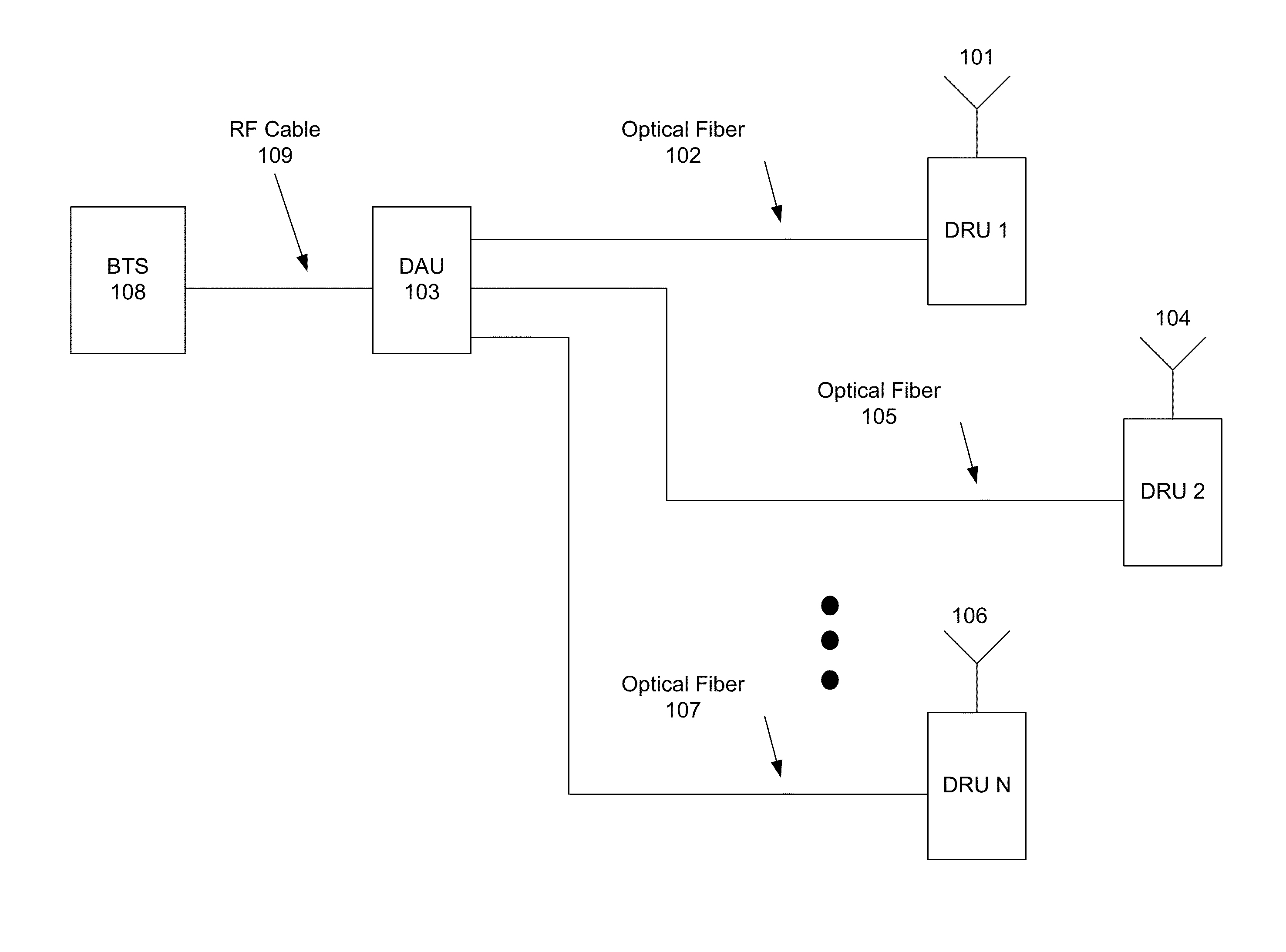
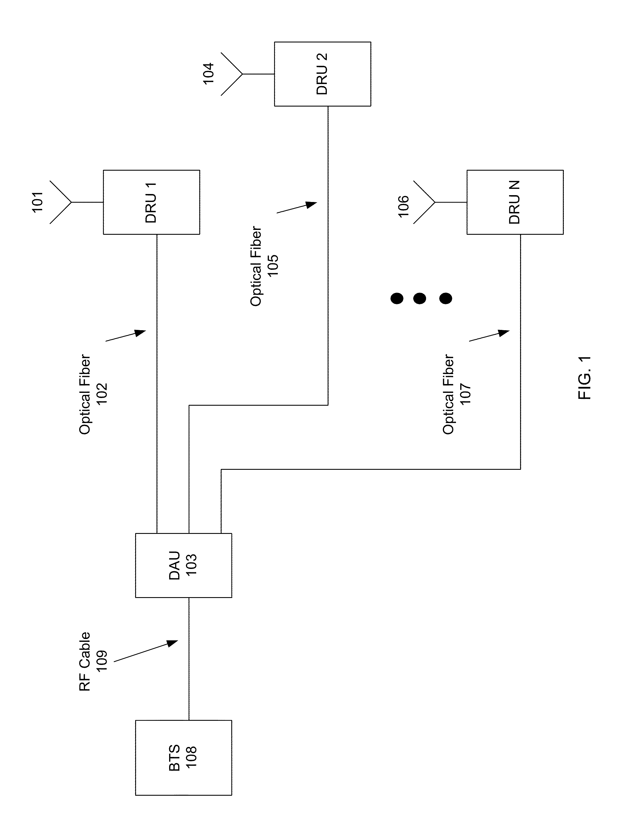
[0034]FIG. 1 shows a block diagram of an exemplary Distributed Antenna System (DAS). Each DRU may receive wireless uplink signals 101, 104, or 106 at its antenna. The DRUs may each be connected to a DAU 103 via an optical fiber 102, 105 or 107, and the DAU 103 may be connected to a BTS 108 via one or more RF cables 109. The DRU may transport the uplink signals to...


PUM


Abstract

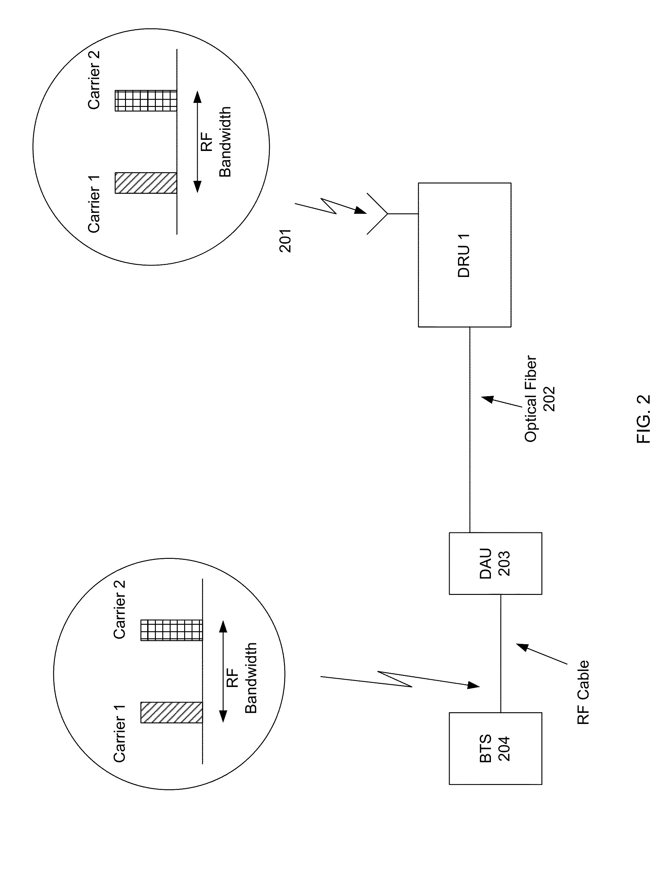
A method for transporting communications signals includes receiving an analog IF signal at a first unit. The analog IF signal includes a first carrier having a first frequency and a first bandwidth and a second carrier having a second frequency different from the first frequency and a second bandwidth. The analog IF signal is converted to a digitally sampled IF signal having the first carrier located in a first Nyquist zone, the second carrier located in a second Nyquist zone, an image of the first carrier located in a third Nyquist zone, and an image of the second carrier located in the third Nyquist zone. The image of the first carrier and the image of the second carrier is transmitted from the first unit to a second unit, where the image of the first carrier and the image of the second carrier is then converted to the analog IF signal.

Description

CROSS-REFERENCES TO RELATED APPLICATIONS[0001]This application claims priority to U.S. Provisional Patent Application No. 61 / 564,211, filed on Nov. 28, 2011, titled “Software Configurable Distributed Antenna System and Method for Bandwidth Compression and Transport of Signals in Noncontiguous Frequency Blocks,” the disclosure of which is hereby incorporated by reference in its entirety for all purposes.BACKGROUND OF THE INVENTION[0002]Wireless communication systems employing Distributed Antenna Systems (DAS) are available. A DAS typically includes one or more host units, optical fiber cable or other suitable transport infrastructure, and multiple remote antenna units. A radio base station is often employed at the host unit location commonly known as a base station hotel, and the DAS provides a means for distribution of the base station's downlink and uplink signals among multiple remote antenna units. The DAS architecture with routing of signals to and from remote antenna units can ...

Claims


Application Information

Patent Timeline
Patent Type & Authority Applications(United States)
IPC IPC(8): H04W72/04
CPCH04W72/04H04B1/40H04B1/50H04B1/0007H04L47/38
Inventor STAPLETON, SHAWN PATRICKKIM, WAN-JONG
Owner DALI SYST LTD
Learn More