
System for forming security markings using structured microdots

Inactive Publication Date: 2014-03-20
EASTMAN KODAK CO
View PDF1 Cites 5 Cited by
  • Summary
  • Abstract
  • Description
  • Claims
  • Application Information

AI Technical Summary

Benefits of technology

The patent describes a new type of small dot on a printing plate that is significantly smaller than traditional microdots. The new dots have a pattern of six or more square pixels each less than 11 microns edge length arranged in a contiguous manner. This new dot structure provides better accuracy and resolution for aligning multiple printing plates in a multicolor or multilayer print. The dots also provide directional confirmation to ensure that the plate is correctly aligned and not rotated or inverted. The patent also discusses alternative options for using structured microdots or adding more pixels to the dots. Overall, the patent presents a new way to improve printing plate accuracy and resolution.

Problems solved by technology

Placing the plates was a highly skilled process and often resulted in mis-register for at least one of the colors.
With the printed dots being as small as 10-20 microns, any shift in registration can cause color shifts, image errors, or interference patterns with a negative impact on the final image.
Such large dots are objectionable when visible in the printed product.

Method used


Image

  • System for forming security markings using structured microdots
  • System for forming security markings using structured microdots
  • System for forming security markings using structured microdots

Examples


Embodiment Construction

[0039]The present invention will be directed in particular to elements forming part of or in cooperation more directly with the apparatus in accordance with the present invention. It is to be understood that elements not specifically shown or described may take various forms well known to those skilled in the art.

[0040]FIG. 5 shows a video camera mounting for a device consisting of two cameras 121, 123 connected to the display. The cameras provide a point of reference in the direction of the cylinder 107 and allow adjustment on the first plate 110, shown in FIG. 6, so the register mark for each side of the plate 111, 112, often still small crosses, are in the camera center. The cameras are locked in position for each following plate to allow register.

[0041]Referring to FIG. 10, some brand owners and packaging buyers objected to relatively large register marks in the artwork, especially as the capabilities and expectations for flexographic printing improved, so a less obvious registe...


PUM


Abstract

A system for forming security markings using structured microdots (154) on a printing plate includes a printhead for forming a first plurality of square spots (156) less than or equal to 11 microns; wherein a first group (157) of the first plurality of square spots is formed in a first pattern (158); and wherein the first pattern is less than or equal to 66 microns and comprises a first microdot.

Description

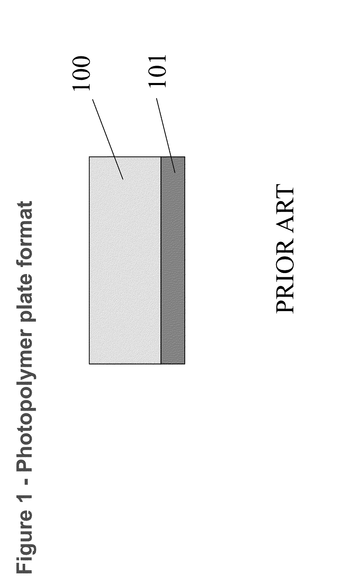
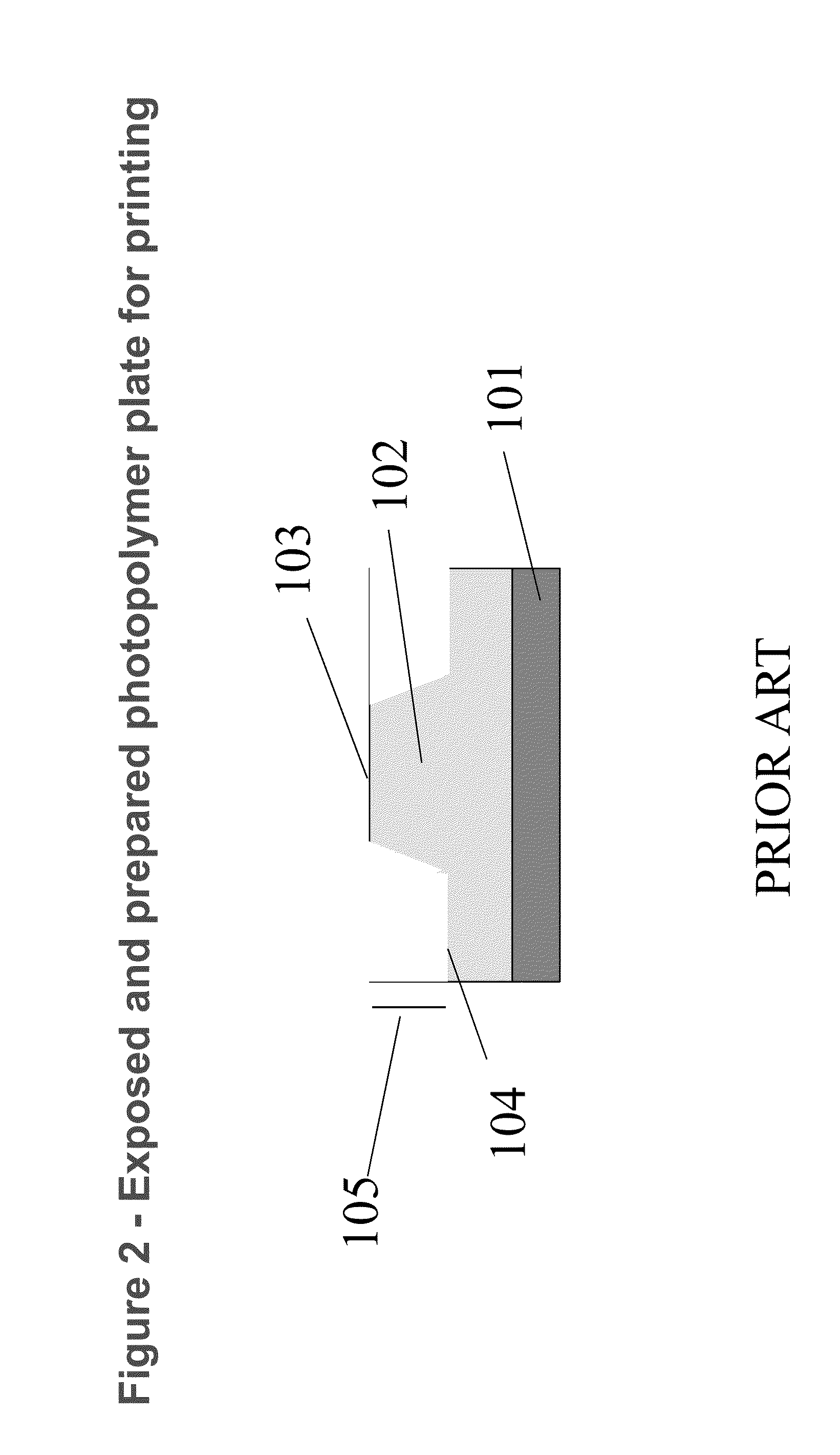
CROSS REFERENCE TO RELATED APPLICATIONS[0001]Reference is made to commonly-assigned copending U.S. patent application Ser. No. ______ (Attorney Docket No. K001035US01NAB), filed herewith, entitled METHOD OF FORMING STRUCTURED MICRODOTS, by Anderson; U.S. patent application Ser. No. ______ (Attorney Docket No. K001281US01NAB), filed herewith, entitled SYSTEM FOR FORMING STRUCTURED MICRODOTS, by Anderson; and U.S. patent application Ser. No. ______ (Attorney Docket No. K001282US01NAB), filed herewith, entitled METHOD OF FORMING SECURITY MARKINGS, by Anderson; the disclosures of which are incorporated herein.FIELD OF THE INVENTION[0002]This invention relates in general to flexographic printing and in particular to using microdots for plate registration.BACKGROUND OF THE INVENTION[0003]The flexographic industry has developed over the years from hand carved rubber plates with no expectations of register control between colors, to use of a photopolymer plate 100, shown in FIG. 1, supporte...

Claims


Application Information

Patent Timeline
IPC IPC(8): B41F7/00
CPCB41F33/0081B41C1/00B41F27/005B41M3/14
Inventor ANDERSON, III, JOHN T.
Owner EASTMAN KODAK CO
Learn More