Eureka AIR delivers breakthrough ideas for toughest innovation challenges, trusted by R&D personnel around the world.

Drapery tube incorporating batteries within the drapery tube, with a stop for facilitating the loading and unloading of the batteries

Active Publication Date: 2014-03-20
CURRENT PROD CORP
View PDF18 Cites 24 Cited by
  • Summary
  • Abstract
  • Description
  • Claims
  • Application Information

AI Technical Summary

Benefits of technology

The invention is a motorized system for moving window coverings, such as blinds, curtains, or draperies. The system can be powered by batteries and has a spring-biased mechanism to help with battery removal and loading. The system also includes a hollow interior or drapery shaft to house the motor and batteries. The patent also describes a battery stop to prevent batteries from being forced out of the tube and a mechanism to prevent power from being supplied to the motor until a trigger is pressed. The technical effects include convenient and controlled battery replacement without having to remove the drapery tube or switch off the motor.

Problems solved by technology

In such cases, the number of components adds complexity to the assembly and cost.

Method used


Image

  • Drapery tube incorporating batteries within the drapery tube, with a stop for facilitating the loading and unloading of the batteries
  • Drapery tube incorporating batteries within the drapery tube, with a stop for facilitating the loading and unloading of the batteries
  • Drapery tube incorporating batteries within the drapery tube, with a stop for facilitating the loading and unloading of the batteries

Examples


Embodiment Construction

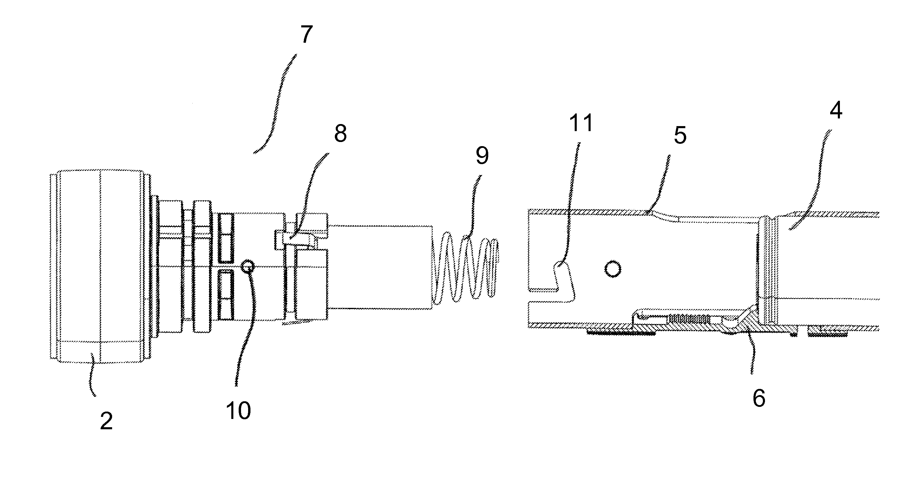
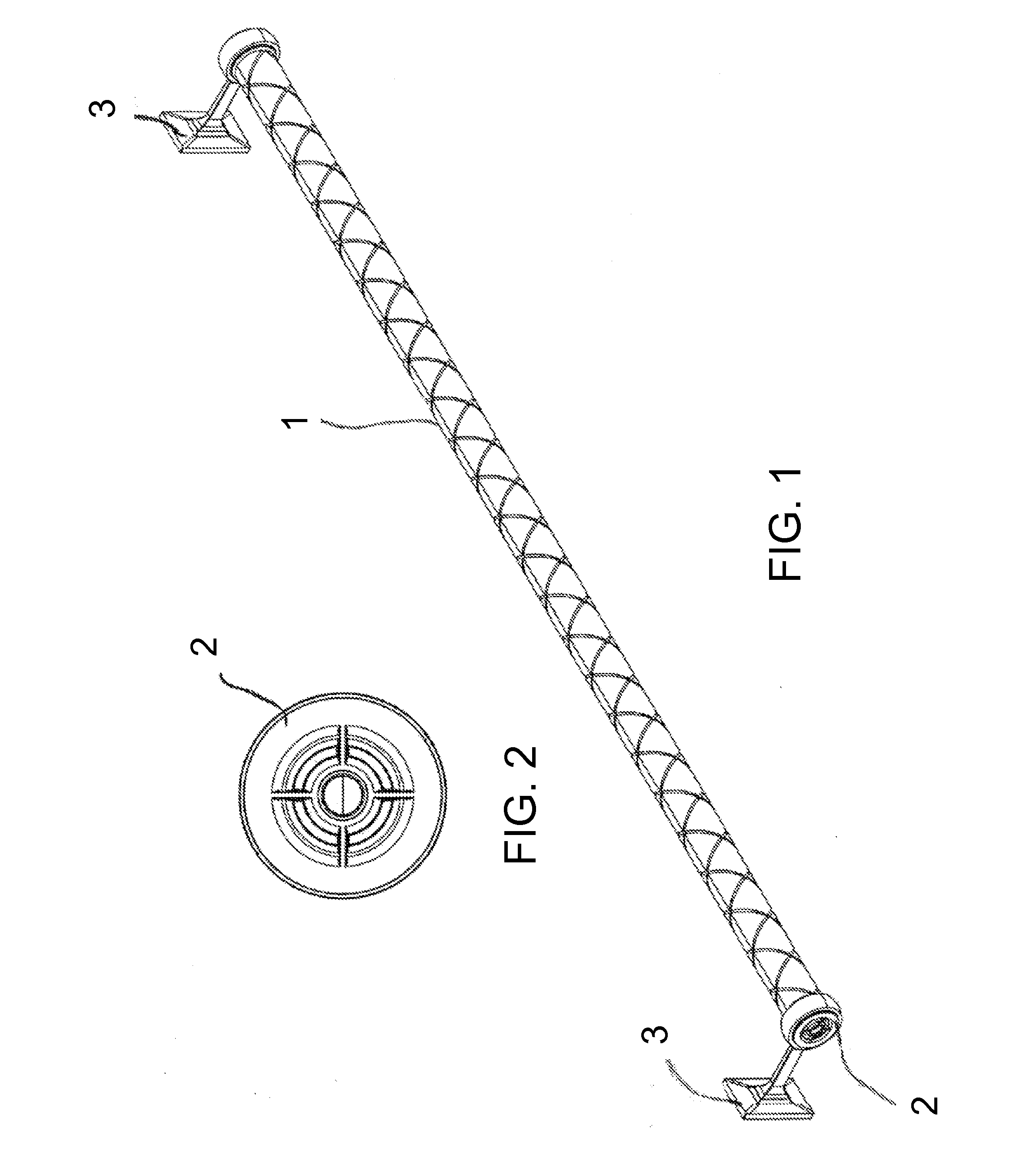
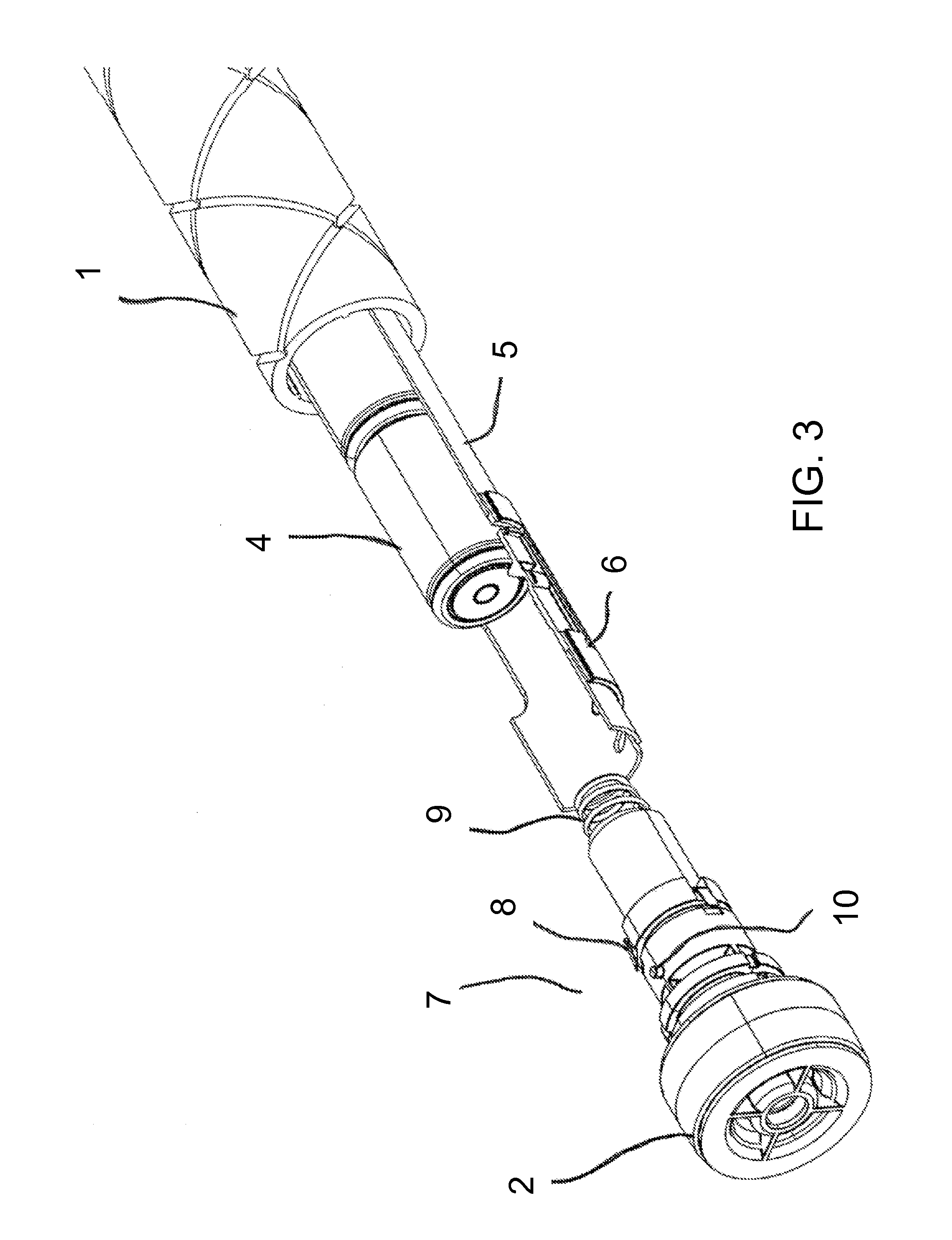
[0031]Specific embodiments will be described in order to illustrate various features that can be incorporated in various embodiments of the subject invention. Referring to FIG. 1 and FIG. 11, the drapery rod or tube 1 is mounted with wall brackets 3 above an opening in a structure such that the drapery can extend and cover the opening. The drapery rod or tube can be motorized for rotating the rod or tube about a longitudinal axis of the rod or tube, and the motor and power supply can be within the rod or tube. In specific embodiments, such as shown in FIG. 1, the motor controls can also be internal to the drapery rod or tube, as taught in U.S. provisional application Ser. No. 61 / 702,093. In specific embodiments, the drapery rod or tube 1 can, optimally, have end caps. The end caps 7 can be plain end caps, and can have compression rings. FIG. 1 shows plain end caps with compression rings 2 and FIG. 11 shows compression rings 2 with finials 23.

[0032]In specific embodiments, the drive ...


PUM


Abstract

Embodiments of the invention relates to a motorized system for moving vertical blinds, curtains, draperies, or other window coverings. Specific embodiments can, optionally, also be manually operated. When motorized, the power supply can be batteries stored or housed in a tube or portion of a shaft, with a spring biased mechanism to assist during removal and / or loading of the batteries. In a specific embodiment, the stop can be triggered by the user to remove one battery at a time, and can allow the user to load batteries in a manner in which the battery or batteries already loaded in the chamber are held in the chamber. A specific embodiment incorporates a drapery tube with a hollow interior, or drapery shaft with one or more hollow portions, to form an enclosure that can house the motor and the power supply, such as batteries. If desired, the motor controls and an optional RF receiver for the motor can also be housed within the tube. In an embodiment, the batteries can be easily changed or replaced through the end of the tube or shaft, wherein the system has a stop, or release trigger, that can allow only one battery at a time to be loaded or unloaded, to assist in loading and unloading the batteries. In an embodiment, an end cap, such as a twist lock end cap can be positioned over the end of the tube or shaft when batteries are not being loaded or unloaded.

Description

BACKGROUND OF INVENTION[0001]Embodiments of the invention relate to a drapery tube that can be used to move curtains or draperies along the tube, incorporating batteries within the drapery tube and a stop for facilitating the load and unloading of the batteries.[0002]There are many types of systems for moving, such as horizontal movement, vertical blind, curtains, and draperies. Some use a series of pulleys, cables, and belts. Others use motors mounted on one end with tracks. In such cases, the number of components adds complexity to the assembly and cost.[0003]U.S. Pat. No. 4,131,831 (Bochenek et al.) teaches a drapery opening and closing system for draw draperies which are movable over a traverse member between an open and closed position by use of a drapery drive system. The opening and closing system has limit switches positioned to be activated when the draperies are opened and closed. A manually settable timer connected to a power source applies power at preset times to a reve...

Claims


Application Information

Patent Timeline
IPC IPC(8): E06B9/72A47H1/02
CPCA47H1/02E06B9/72A47H5/06A47H23/00B23B3/00B23B5/08B23B29/26B23Q1/766E06B9/40B23B2220/12B23B2220/445B23B2215/72Y10T82/10Y10T29/49826A47H13/02A47H2001/0215
Inventor MULLET, WILLIS JAYFOX, MICHAEL D.
Owner CURRENT PROD CORP
Why Eureka
Eureka Blog
Learn More