Method for adjusting a parking brake in a vehicle

a technology for parking brakes and brakes, applied in electrodynamic brake systems, brake systems, transportation and packaging, etc., can solve problems such as motors at a standstill, and achieve the effect of efficient brake application and release process

Active Publication Date: 2014-03-20
ROBERT BOSCH GMBH
View PDF11 Cites 9 Cited by
  • Summary
  • Abstract
  • Description
  • Claims
  • Application Information

AI Technical Summary

Benefits of technology

[0004]It is an object of the present invention to employ simple measures to efficiently c

Problems solved by technology

Basically, however, the braking process may be begun already upon approaching of the en

Method used


Image

  • Method for adjusting a parking brake in a vehicle
  • Method for adjusting a parking brake in a vehicle
  • Method for adjusting a parking brake in a vehicle

Examples


Embodiment Construction

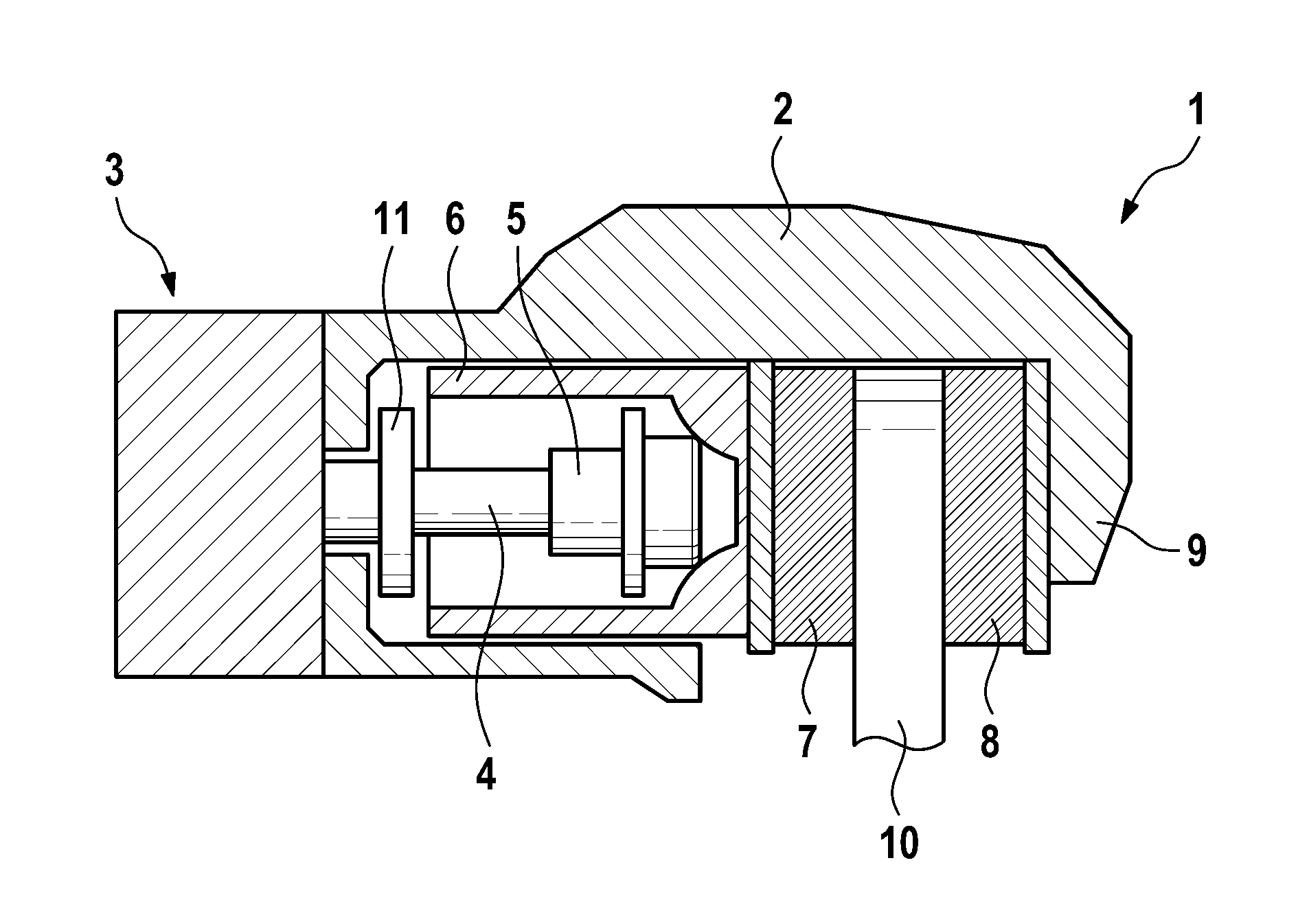
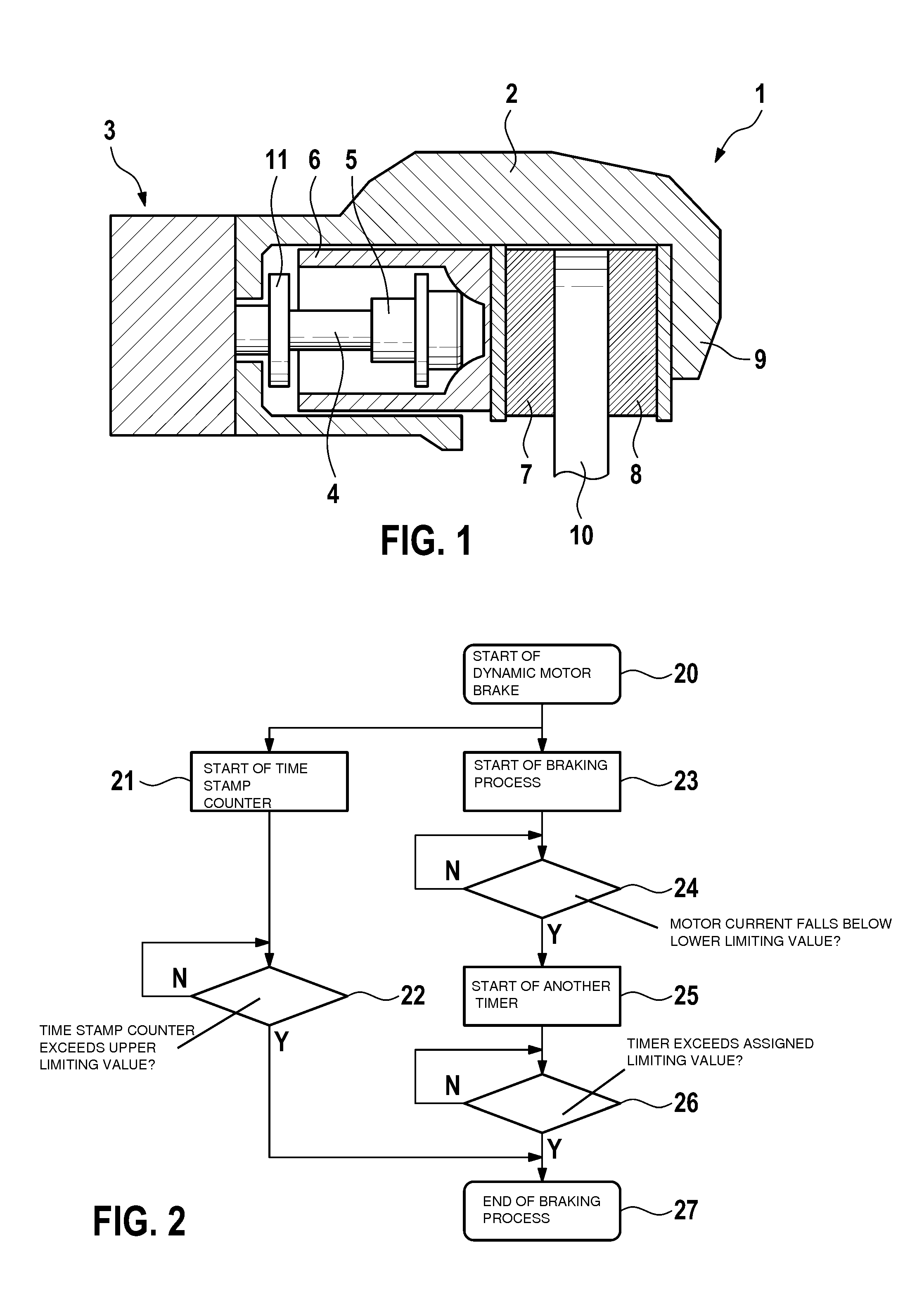
[0021]FIG. 1 shows an electromechanical parking brake 1 for setting a vehicle at standstill. Parking brake 1 includes a caliper assembly 2 having a caliper 9 which reaches over a brake disk 10. As actuator, parking brake 1 has an electromotor as a brake motor 3 which rotationally drives a spindle 4 upon which a spindle component 5 designed as a spindle nut is rotationally mounted. In response to a rotation of spindle 4, spindle component 5 is axially adjusted. Spindle component 5 moves within a brake piston 6 which bears a brake pad 7 that is pressed by brake piston 6 against brake disk 10. Located on the opposite side of brake disk 10 is another brake pad 8 which is held immovably in place on caliper 9.

[0022]Within brake piston 6, spindle component 5 may move axially forwards toward brake disk 10, respectively, in response to an opposite rotational movement of spindle 4, axially rearwards until reaching a limit stop 11. To generate a clamping force, spindle component 5 acts upon th...


PUM


Abstract

In a method for adjusting a parking brake, which includes an electromechanical braking device having an electric brake motor, the brake motor is braked upon reaching an end position.

Description

CROSS REFERENCE TO RELATED APPLICATION[0001]The present application is the national stage entry of International Patent Application No. PCT / EP2012 / 051182, filed on Jan. 26, 2012, which claims priority to Application No. DE 10 2011 006 120.7, filed in the Federal Republic of Germany on Mar. 25, 2011.FIELD OF INVENTION[0002]The present invention relates to a method for adjusting a parking brake in a vehicle.BACKGROUND INFORMATION[0003]Parking brakes in vehicles are known for generating a clamping force in order to set the vehicle at standstill. German Application No. DE 103 61 042 describes a parking brake having an electromechanical design that includes an electric brake motor which drives a brake piston to act axially by way of a brake pad against a brake disk. Upon application of the brake, the electric brake motor is actuated until a desired clamping force is reached. To release the parking brake, the brake motor is driven in the opposite direction and actuated until the brake pad...

Claims


Application Information

Patent Timeline
IPC IPC(8): F16D65/18
CPCF16D65/18B60T13/588B60T13/662B60T13/741
Inventor BAEHRLE-MILLER, FRANKPUTZER, TOBIAS
Owner ROBERT BOSCH GMBH
Why Eureka
Try Eureka