Supercharge Your Innovation With Domain-Expert AI Agents!

Magneto-rheological damping assembly

a damping assembly and magneto-rheological technology, applied in the direction of spring/damper, shock absorber, vibration suppression adjustment, etc., can solve the problems of inability to achieve sufficient cancellation of flux across the main gap in the off-operation state, undesirably small damping force, undesirably high damping force, etc., to achieve low minimum damping force, prevent flux leakage, and high turn-up ratio

Active Publication Date: 2014-03-20
BEIJING WEST IND CO LTD
View PDF4 Cites 5 Cited by
  • Summary
  • Abstract
  • Description
  • Claims
  • Application Information

AI Technical Summary

Benefits of technology

The invention provides a magneto-rheological damping assembly with an auxiliary gap between the permanent magnets and the internal pole segment to prevent flux leakage when the assembly is in the off operating state. The internal location of the auxiliary gap allows for complete cancellation of flux from the permanent magnets and allows the assembly to be filled with fluid during assembly. The invention provides a higher turn-up ratio and can be manufactured with different radial lengths to tune the damping range for various purposes.

Problems solved by technology

This is a necessary element of the design because without the auxiliary gap, when it is desirable for flux to travel across the main gap (when the device is not in the off operating state), most of the flux would get short circuited into the core rather than passing across the main gap, leading to an undesirably small damping force.
An identified problem of the prior art is that due to the location of the auxiliary gap, sufficient cancellation of the flux across the main gap is not attainable in the off-operating state due to a leakage of flux from the permanent magnets across the main gap.
This is particularly problematic because it results in an undesirably high damping force when the assembly is in the off operating state and it prevents filling of the MR assembly with fluid through the main gap during assembly.

Method used


Image

  • Magneto-rheological damping assembly
  • Magneto-rheological damping assembly
  • Magneto-rheological damping assembly

Examples


Embodiment Construction

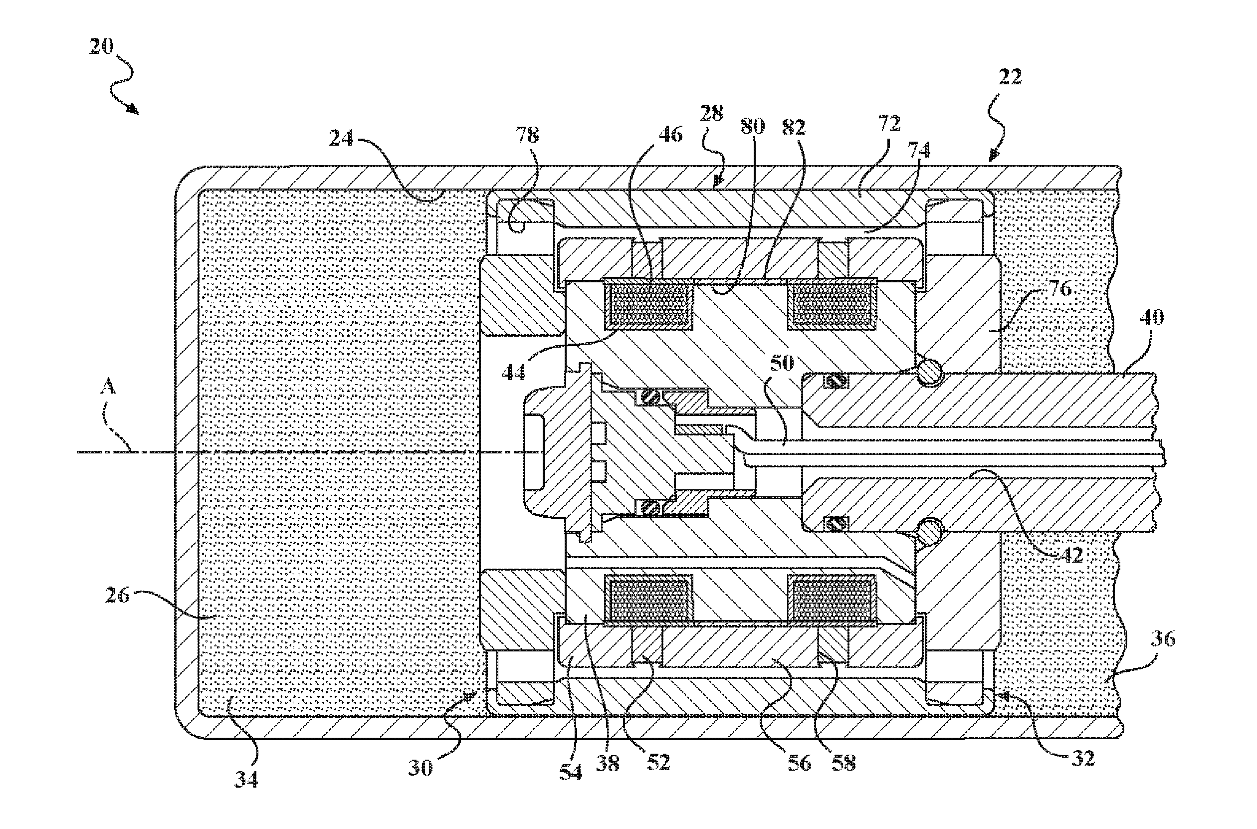
[0020]Referring to the Figures, wherein like numerals indicate corresponding parts throughout the several views, a magneto-rheological damping assembly 20 is generally shown.

[0021]The assembly 20 includes a cylindrical shaped housing 22 that extends along an axis A and presents an open interior 24 containing a magneto-rhological fluid 26. A cylindrical shaped piston 28 is slidably disposed is in the open interior 24 of the housing 22. It should be appreciated that the piston 28 and the housing 22 could have other cross-sectional shapes however they should correspond with and complement one another. The piston 28 has a compression end 30 and a rebound end 32 and the housing 22 defines a compression chamber 34 on the compression end 30 of the piston 28 and a rebound chamber 36 on the rebound end 32 of the piston 28.

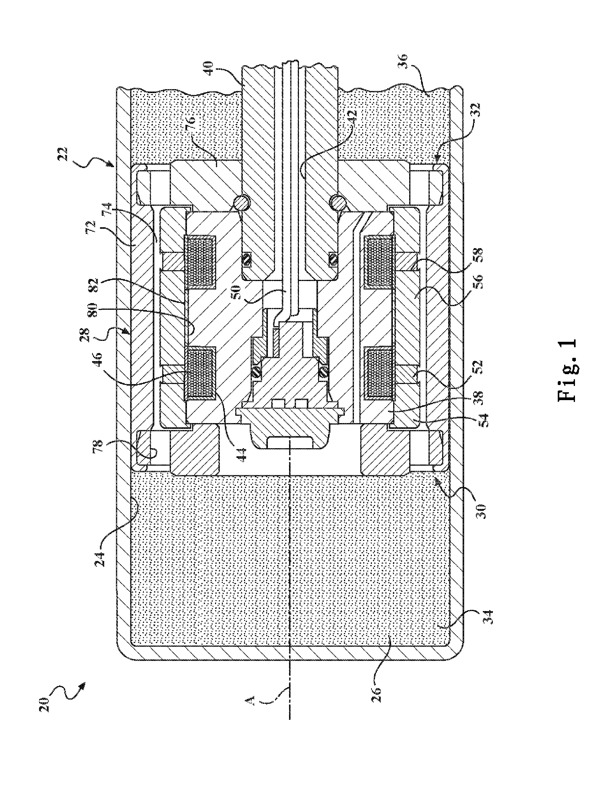
[0022]The piston 28 defines a steel cylindrical shaped core 38. It should be appreciated that the core 38 could be constructed of other materials, however the chosen materi...


PUM


Abstract

A magneto-rheological damping assembly including a piston (28) defining a core (38). A pair of spaced electromagnets (46) are disposed about the core (38) and are connected to a controller (48) for selectively generating a magnetic flux. A pair of permanent magnets (52) are disposed about the electromagnets (46) and a pole segment (54;154;56;156) is disposed therebetween. A main gap (74) extends through the piston (28) through which magneto-rheological fluid (26) is conveyed. Flux generated by the magnets controls the viscosity of the fluid in the main gap (74) to control the damping force of the assembly. The controller (48) defines an off operating state for cancelling the flux from the permanent magnets (52) across the main gap (74). The core (38) and the pole segment (54;154;56;156) define a closed auxiliary gap (80) extending axially between the electromagnets (46) and radially between the core (38) and the internal pole segment (56) for preventing leakage of flux across the main gap (74) when the assembly is in the off operating state.

Description

BACKGROUND OF THE INVENTION[0001]1. Field of the Invention[0002]A magneto-rheological damping assembly.[0003]2. Description of the Prior Art[0004]Magneto-rheological (MR) damping assemblies are well known in the art. Such devices are known and used in the automotive field in vehicle suspension systems in the form of shock absorbers, struts, and other motion or vibration damping structures. MR Dampers use magneto-rheological, or MR fluid, which exhibits a thickening behavior (a rheology change) upon being exposed to magnetic fields of a sufficient strength. The higher the magnetic field strength to which the MR fluid is exposed, the higher the viscosity of the fluid, and the higher the damping force of the device.[0005]One such assembly is shown in U.S. Patent Application 2010 / 0089711 (Hereinafter known as the '711 application). The '711 application discloses a piston extending along an axis defining a compression end and a rebound end. The piston defines a core. An electromagnet is ...

Claims


Application Information

Patent Timeline
Patent Type & Authority Applications(United States)
IPC IPC(8): F16F9/53
CPCF16F9/535
Inventor NEHL, THOMAS WOLFGANGFOISTER, ROBERT T.BAILLY, FREDERICTESSIER, GUY
Owner BEIJING WEST IND CO LTD
Features
  • R&D
  • Intellectual Property
  • Life Sciences
  • Materials
  • Tech Scout
  • Unparalleled Data Quality
  • Higher Quality Content
  • 60% Fewer Hallucinations
Learn More