Two-stage clamp for glass transport

a clamping mechanism and glass technology, applied in the field of clamps, can solve the problems of loss of nuts, bolts and washers of such clamping mechanisms, inconsistent uniformity of tightening, and difficulty for a glove wearer to have the dexterity required to quickly hand-tighten such mechanisms, etc., to facilitate one-time adjustment of the mechanism and facilitate operation.

Inactive Publication Date: 2014-03-20
MCDONALD ALEX
View PDF14 Cites 3 Cited by
  • Summary
  • Abstract
  • Description
  • Claims
  • Application Information

AI Technical Summary

Benefits of technology

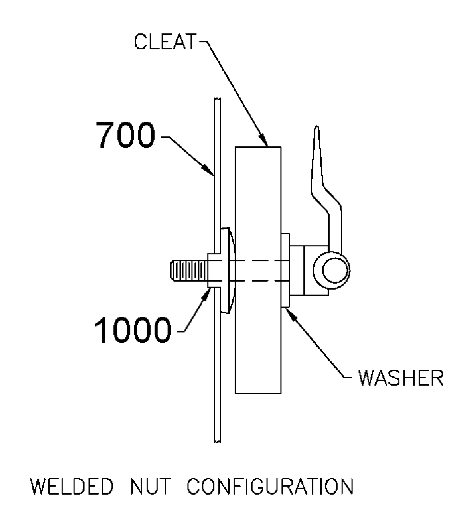
[0012]Glass or other sheet material is clamped in place by manually pushing a rubber-surfaced clamping cleat against the glass with the desired second-stage clamping force, and then clamping the rubber member in place by rotating a handle which is attached to a cam which provides the second-stage clamping force. A threaded shaft facilitates one-time adjustment of the mechanism such that subsequently the second-stage clamping force of the cam will be consistent in the clamped state and will not require adjustment the next time the clamp is used. The clamp may easily be operated by a gloved hand.

Problems solved by technology

There are several drawbacks of the above-described clamping mechanism.
During disassembly, or during transport with the rack empty and clamps not tightened, the nuts, bolts, and washers of such clamping mechanisms may be subject to loss.
Further, it may be difficult for a person wearing a glove to have the dexterity required to hand-tighten such a mechanism quickly, and it is desirable for glass workers to wear gloves for safety.
Another potential problem is that tightening is “by feel”, and thus uniformity of tightening is likely to be inconsistent.
While this type of clamping mechanism is quick to operate and is typically not subject to parts loss (because it is meant to remain attached to the stake it is mounted on), this mechanism is quite expensive compared to simple glass clamping mechanisms shown in FIGS. 4 and 5, and thus is not nearly as frequently used.

Method used


Image

  • Two-stage clamp for glass transport
  • Two-stage clamp for glass transport
  • Two-stage clamp for glass transport

Examples


Embodiment Construction

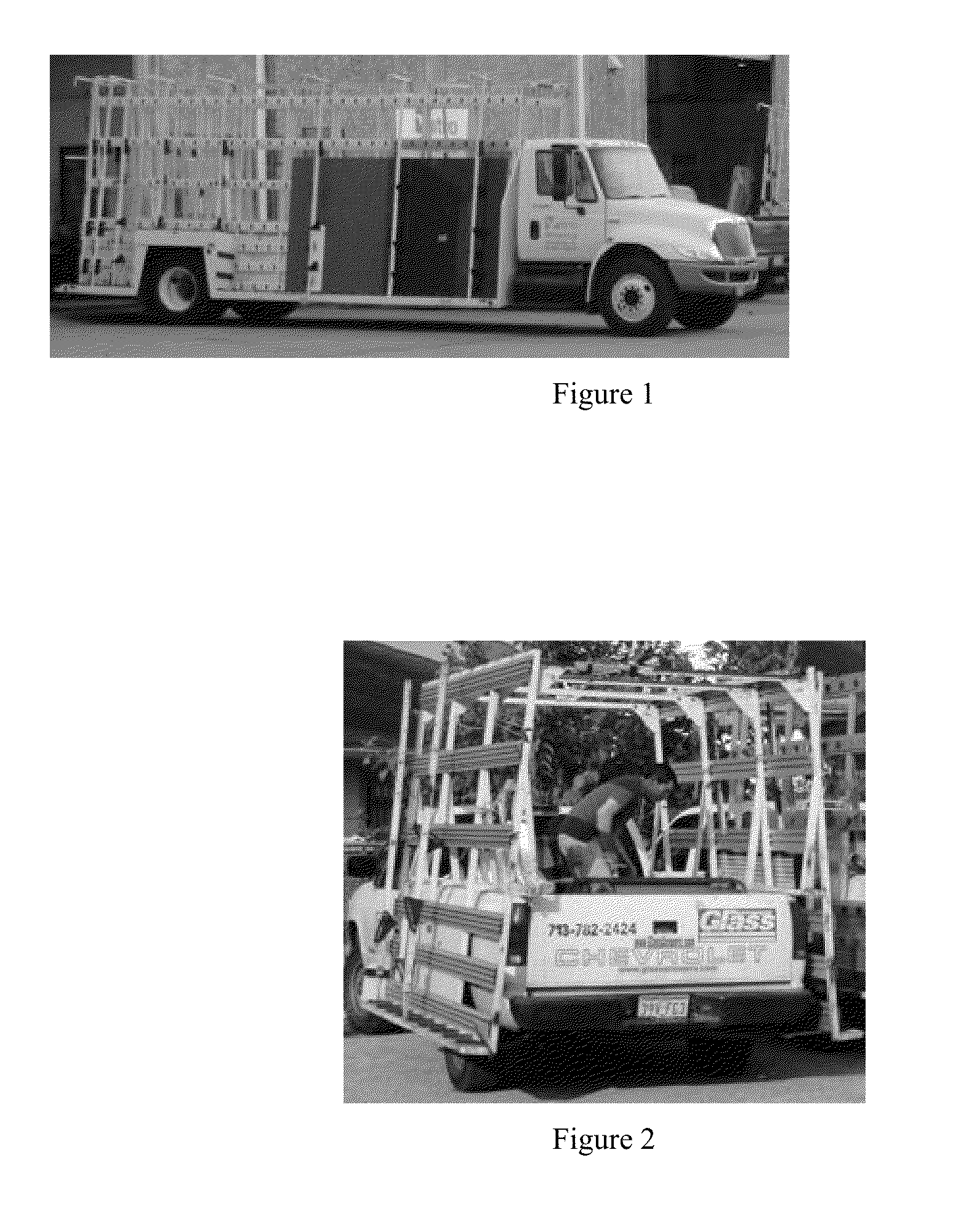
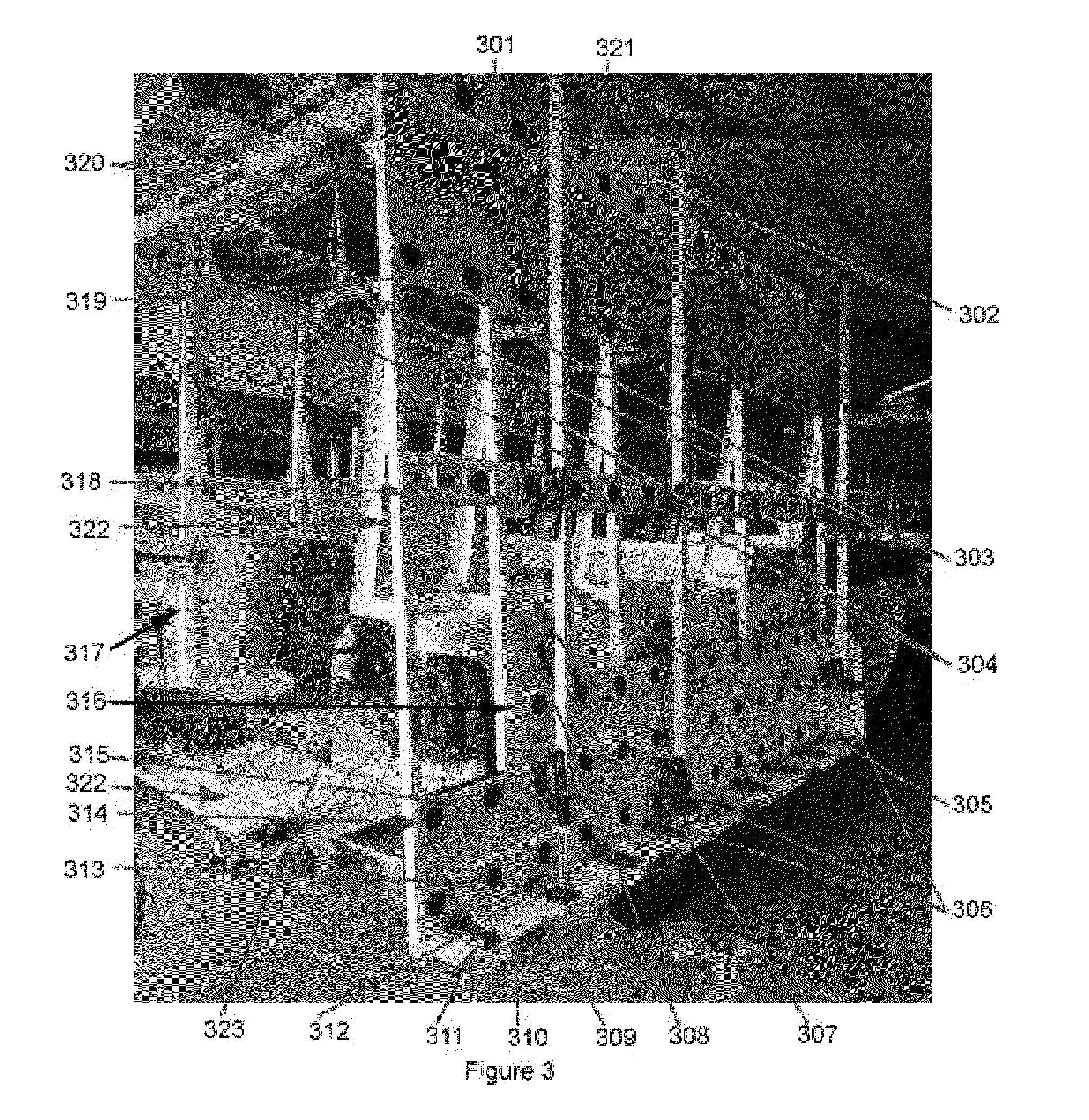
[0029]The term “glass rack” as used in this document shall be construed to mean a rack suitable for transporting glass or other sheet material, or stone slabs or the like. FIG. 3 is a photo of a typical modern light-duty glass delivery truck with a glass rack installed. Mounting rail 307 bolts to truck bed wall rail 308 and supports the weight of the glass rack on truck bed wall rail 308. The plane in which the interface between mounting rail 307 meets truck bed wall rail 308 shall be referred to in this document as the “primary plane of attachment”.

[0030]Glass or other sheet material which is loaded on the rack rests edge-wise on rubber pads 311 and the majority of the weight of the glass is transferred to lower support rail 309 through pads 311. A small fraction of the weight of glass or other sheet material loaded on the rack rests on surface pads 314 (also sometimes called “buttons”), which are mounted along first (lower) face rail 313, second face rail 315, third face rail 316,...


PUM


Abstract

A two-stage clamp for holding glass in place during transport is disclosed. Glass is clamped in place by manually pushing a rubber clamping member against the glass with the desired second-stage clamping force, and then clamping the rubber member in place by rotating a handle which is attached to a cam which provides the second-stage clamping force. A threaded shaft facilitates one-time adjustment of the mechanism such that subsequently the second-stage clamping force of the cam will be consistent in the clamped state and will not require adjustment the next time the clamp is used. The clamp may easily be operated by a gloved hand.

Description

FIELD OF THE INVENTION[0001]The field of the invention relates to transport systems for sheet materials, glass racks, clamps, and more specifically to clamping sheets of glass in place during transport.BACKGROUND OF THE INVENTION[0002]For as long as glass windows have been commercially available, various methods and apparatus have evolved for transporting sheets of glass from manufacturer to distributor, and from distributor to consumer. Modern consumers of sheet glass are mainly businesses, since most glass which gets installed in residences is already pre-installed in window frames, mirror frames, and the like, whereas windows and mirrors installed in businesses are often large sheets of glass which are delivered un-framed.[0003]There are two classes of modern glass delivery trucks: large, heavy-duty large-capacity glass trucks which are used for delivering glass from manufacturers to distributors (or to large construction sites during initial construction), and small, lighter-dut...

Claims


Application Information

Patent Timeline
Patent Type & Authority Applications(United States)
IPC IPC(8): B60R9/02
CPCB60R9/02B60P3/002
Inventor MCDONALD, ALEX
Owner MCDONALD ALEX
Why Eureka
Try Eureka