
Jet Pump Stabilizer

a stabilizer and jet pump technology, applied in the field of clamps, can solve the problems of low static pressure of the driving flow, unstable pressure fluctuations, abnormal wear of the jet pump assembly, etc., and achieve the effect of restricting coolant leakag

Inactive Publication Date: 2014-03-20
AREVA NP INC
View PDF10 Cites 11 Cited by
  • Summary
  • Abstract
  • Description
  • Claims
  • Application Information

AI Technical Summary

Benefits of technology

The invention is a device that prevents coolant leakage in a jet pump. It uses a clamp body that can be easily placed without removing any assembly components. The device also includes two U-clamps that are connected to the clamp body and each one surrounds a separate jet pump pipe. A wedge subassembly is positioned between the riser pipe and the mixer pipe. The device prevents movement of the mixer pipe and reduces vibration caused by flow. The connections between the clamp body and the U-clamps can accommodate any misalignment between the pipes. Overall, this device helps to improve the stability of jet pumps.

Problems solved by technology

This increase in fluid flow velocity results in lower static pressure of the driving flow.
In addition, unstable pressure fluctuations result from the passage of coolant through the slip joint 12 to the lower pressure downcomer annulus.
Consequently, abnormal wear of jet pump assembly 1 components has been experienced at several BWR plants.

Method used


Image

  • Jet Pump Stabilizer
  • Jet Pump Stabilizer
  • Jet Pump Stabilizer

Examples


Embodiment Construction

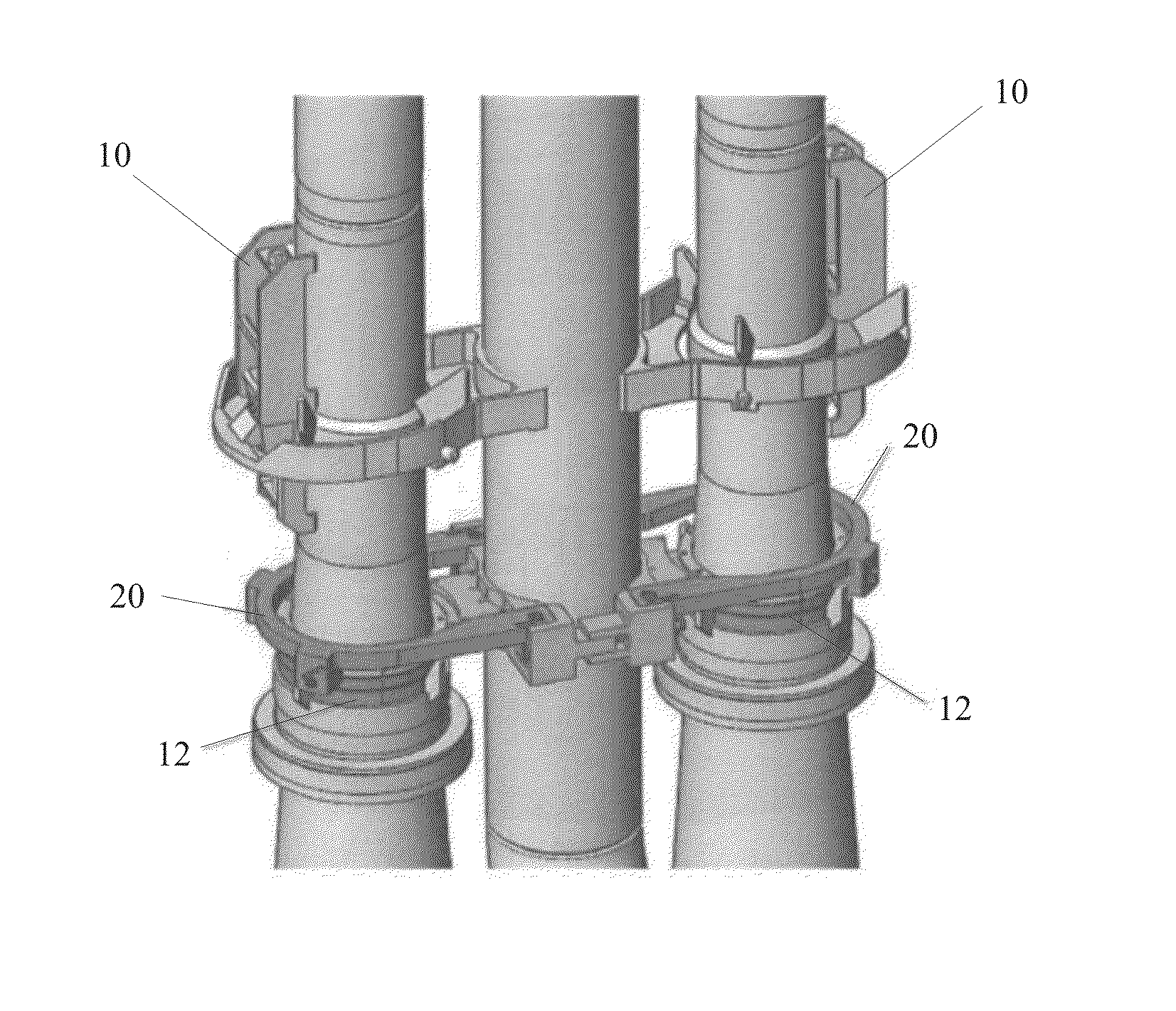
[0029]FIG. 3 shows a slip joint clamp 20 of the present invention, and FIG. 4 shows a slip joint clamp subassembly 30 thereof. The subassembly 30 includes inboard 31 and outboard 32 semicircular clamp segments, which are joined together by a pair of slip joint bolts 40 and bolt keepers 41 to form a circular clamp ring 33. A seal ring 36 includes inboard 34 and outboard 35 semicircular seal segments that are joined to the clamp ring 33 by several guide pins 37. Captive to the guide pins 37 are spring elements 38, which collectively provide a separation force between the stationary clamp ring 33 and the moveable seal ring 36. The seal ring 36 is designed to move axially upward in response to the thermal growth of the diffuser 6 relative to the inlet mixer 5. This upward axial movement is resisted by the compressive action of the spring elements 38.

[0030]The inboard 31 and outboard 32 semi-circular clamp segments are configured with an opposing tongue-and-groove design to ensure proper...


PUM


Abstract

A jet pump stabilizer is disclosed and claimed. The stabilizer includes a clamp body that is affixed about the riser pipe. Two U-clamps are connected to the clamp body, each U-clamp positioned about a jet pump mixer section. A wedge assembly is positioned between the clamp body and each mixer pipe, cooperating with the clamp body and U-clamps to laterally restrain the mixer sections. A clamp ring is positioned about each mixer section and retained in place by the U-clamps, wedge assemblies, and clamp body. A sealing ring is moveably connected to the clamp ring such that it is biased toward engagement with the jet pump diffuser. Seals provided on the stabilizer engage the jet pump assembly above and below the slip joint, preventing vibration-inducing leakage through the slip joint.

Description

CROSS-REFERENCE TO RELATED APPLICATIONS[0001]This patent application claims the benefit of U.S. Provisional Patent Application No. 61 / 703,734 filed on Sep. 20, 2012, which is incorporated herein by reference in its entirety.BACKGROUND OF THE INVENTION[0002]1. Field of the Invention[0003]The present invention relates to a clamp, and, more particularly, the present invention relates to a repair device for use, for example, with boiling water reactor jetpumps.[0004]2. Description of the Related Art[0005]While the present invention may be used in a variety of industries, the environment of a boiling water reactor (BWR) nuclear power plant will be discussed herein for illustrative purposes. In a BWR, a steam-water mixture is produced when reactor coolant (water) moves upward through the core, absorbing heat produced by the fuel. The steam-water mixture leaves the top of the core and enters a moisture separator, where water droplets are removed before the steam is allowed to enter the ste...

Claims


Application Information

Patent Timeline
Patent Type & Authority Applications(United States)
IPC IPC(8): F04F5/44
CPCF04F5/44F04F5/46F04F5/54
Inventor JENSEN, GRANT CLARKMARKHAM, KENNETH WADEBUSIC, THOMAS NEWLAND
Owner AREVA NP INC
Learn More