Infusion Rotary Peristaltic Pump

a peristaltic pump and rotary technology, applied in the direction of positive displacement liquid engine, intravenous device, other medical devices, etc., can solve the problems of high parts cost, complicated assembly, unnecessary energy consumption, etc., and achieve the effect of reducing power consumption, reducing friction and power consumption, and no friction

Active Publication Date: 2014-03-20
MICREL MEDICAL DEVICES SA
View PDF2 Cites 41 Cited by
  • Summary
  • Abstract
  • Description
  • Claims
  • Application Information

AI Technical Summary

Benefits of technology

[0013]The pump according to the present invention uses a consumable infusion set which includes the largest part of an infusion mechanism and all the accessories needed for a safe infusion in various embodiments depending on the type of infusion and is provided in one cartridge which may be assembled in an auto-matic indexing machine so as to minimize costs.
[0018]According to the present invention, each layer has a discrete functional role in the device. The present invention uses the aforementioned three epicyclic similarities to make possible their use in a single three-functions-arrangement which define a planet roller / gear arrangement including a central or sun gear / roller, a planet gear / roller and an annulus system defining an external peristaltic tubing and pressure drum / bearing annulus / gear annulus. This arrangement according to the present invention requires only a minimum power consumption since there is no substantial friction of pressure rollers to a central driving rotor and there is no use of a driving carrier as in the prior art which otherwise would induce friction. Due to a high accuracy of the angular position of the rollers resulting from the operation of the epicyclic gear head, the infusion is absolutely predictable and accurate. Further, the intrinsically active smooth rolling of the rollers on and along the resilient tubing prevents the tubing from deforming and pulling.
[0020]In the roller bearing layer, a pumping force onto the resilient tubing due to pressure against the drum is compensated and eliminated creating a radial reaction force from the opposite bearing ring due to a serial chain reaction transfer of the three cylinders in contact on the same rotating plane, so that there is no friction on the central driving axis. This result in a dramatic decrease of power consumption while at the same time the very important nominal distance between the gears is maintained which also contributes to the decrease of the friction and power consumption, which is otherwise not possible without a carrier.
[0021]The pumping layer preferably includes only two pressure rollers and a central driving cylinder, wherein the resilient tubing is accommodated within a cavity of the drum having preferably a “”-shaped cross section, so that the roller-tubing compression contact line when squeezing the tubing (major compression) would be spaced by a proper radial distance so as to achieve the desired nominal downstream pressure. Such line is not necessarily at the same radial distance from the center of the bearings, but it has been found that the radial distance may be shorter for one type of tubing and larger for another type of tubing so that in the pump layer the roller is provided with a smaller diameter (insert) in the first case or with a larger diameter (excess) in the second case. Such a solution minimizes the occurrence of friction from the roller onto the tubing.

Problems solved by technology

In the prior art, consumable pump sets contain many parts to be welded in series, such as filters, flows clamps, anti-syphon valves, and Y-connections for other tubings, i.e. many parts which are to be placed in series with an intermediary infusion tubing and many junctions of parts which must be handmade since an automatic production is too difficult, resulting in high parts costs and complicated assembly.
The vertical parts of the “O” cross-section of the tubing are essentially not made to be folded, and in the linear or rotary peristaltic pumps of the prior art an unnecessary consumption of energy occurs because of the resilient tubing section form.

Method used


Image

  • Infusion Rotary Peristaltic Pump
  • Infusion Rotary Peristaltic Pump
  • Infusion Rotary Peristaltic Pump

Examples


Embodiment Construction

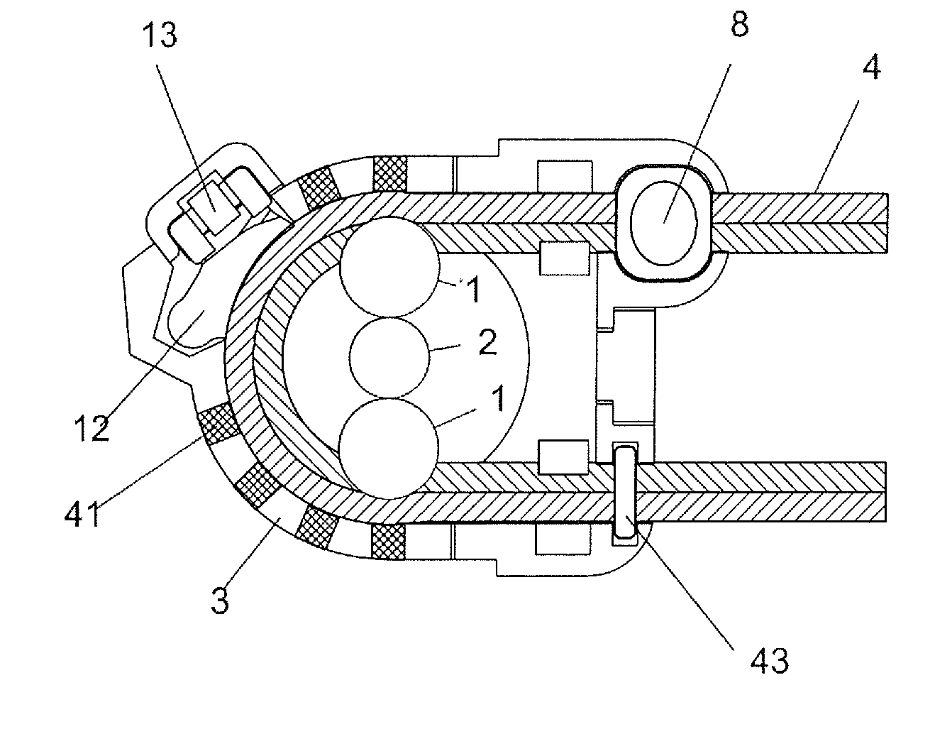
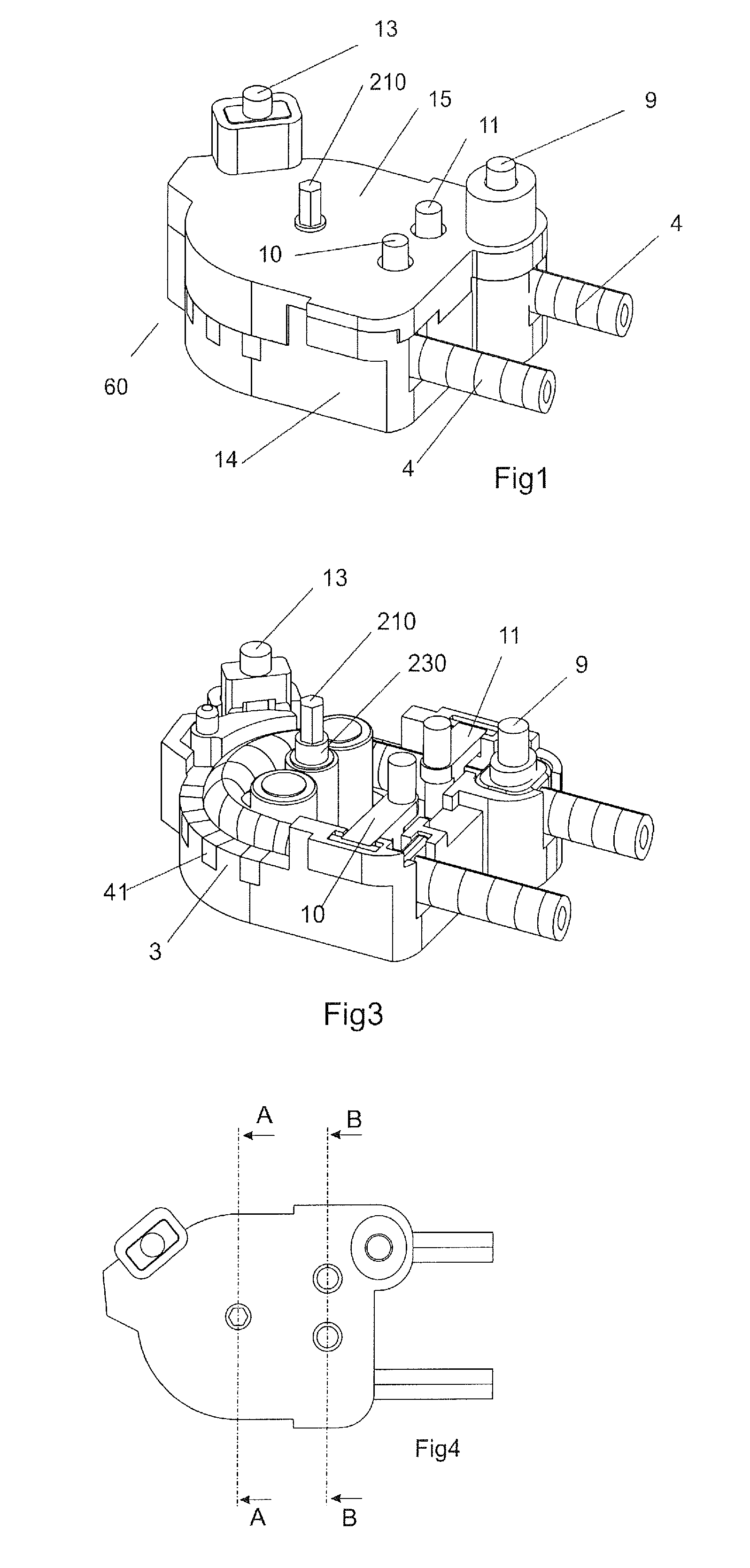
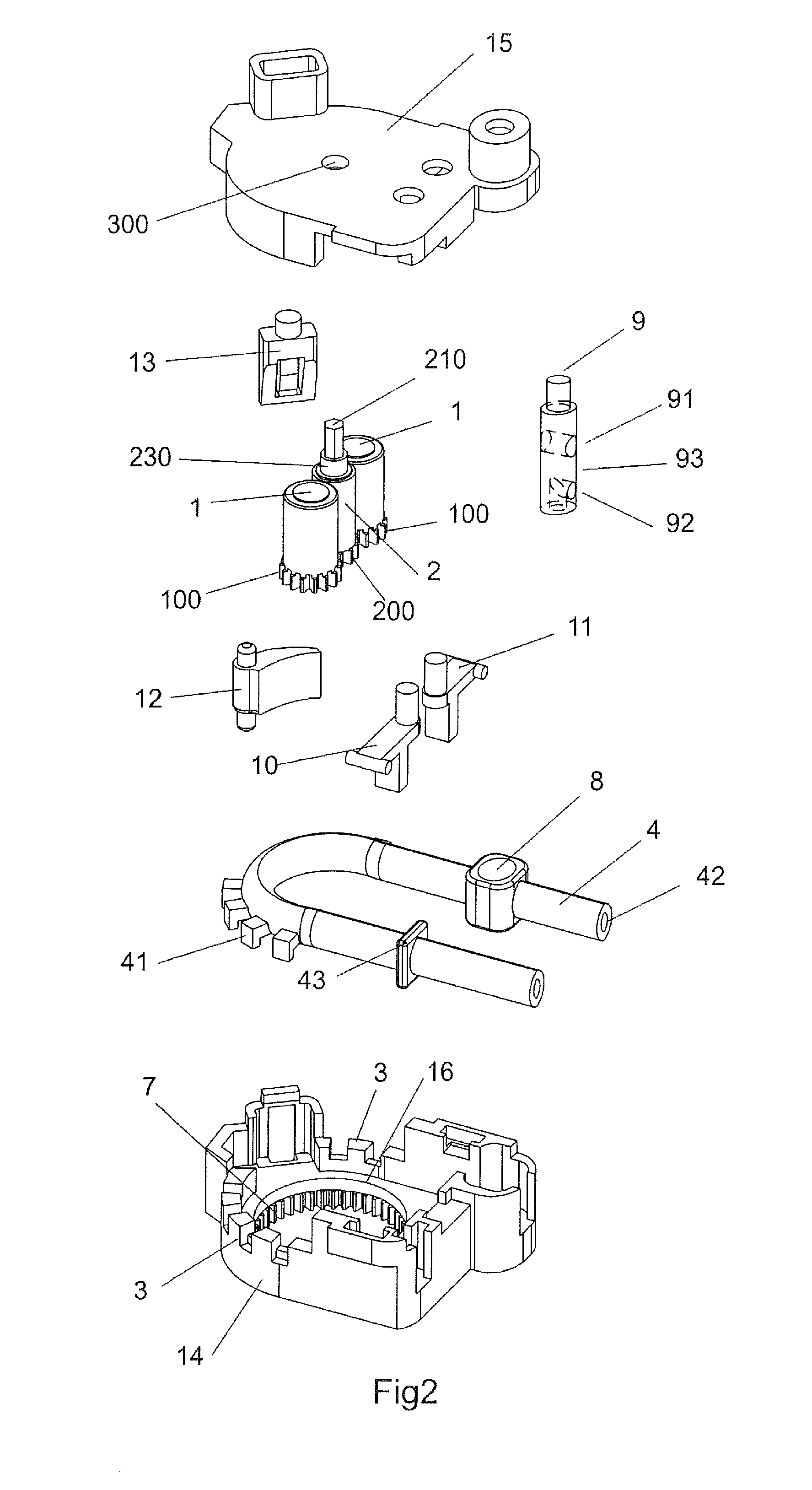
[0050]In more detail, the preferred embodiment of the rotary peristaltic mechanism 60 has preferably two snap-fitting lower and upper parts 14, 15 of a housing in which all other mechanism parts are included wherein the lower and upper parts 14, 15 define lower and upper covers of the housing and therefore commonly form the housing itself. Three cylindrical rollers 1, 2, 1 each having a gear 100, 200 at its bottom, are provided as combined driving and pumping elements, and include two planet rollers 1 of same diameter and one central roller 2, wherein all the cylindrical rollers 1, 2 are arranged in the same (rotating) plane with their rotational axis being parallel to each other and the gear / diameter ratio between the central gear 200 at the bottom of the central roller 2 and to the planet gears 100 at the bottom of the planet rollers 1 determines the reduction ratio of the rotation of the planet rollers 1 over the rotation of the central roller 2. Preferably there is no carrier to...


PUM


Abstract

An infusion pump comprises at least three operating layers. A first layer includes epicyclic gear means comprising a rotatable central gear, a stationary outer ring gear, and movable planet gears arranged between the central gear and the ring gear in movable engagement with the central and ring gears. A second layer includes roller bearing means comprising a stationary outer ring and a movable inner roller arrangement in movable arrangement with the outer ring and coupled with the epicyclic gear means to provide a rotational bearing for the central and planet gears. A third layer includes rotary peristaltic pump means comprising stationary flexible tubing which includes a bent portion having an essentially part-cycle form and a rotor having engagement elements to squeeze the bent portion during rotation for a pump action, wherein the rotor is coupled with the central gear to transfer torque from the central gear to the rotor.

Description

BACKGROUND OF THE INVENTION[0001]The present invention relates to an infusion pump device.[0002]In medical practice, infusion pumps have been used in various ways to pump and forward liquid pharmaceutical substances, wherein the oldest method using a rotary peristaltic pump has been set up in 1881 which pump comprises an elastic pipe fixed in the edges of a “U”, a rotating spool, peripheral rotors in the rounded portion of the “U”, and a tightened rubber used to close the free flow and to pump the enclosed liquid to an exit nozzle (cf. U.S. Pat. No. 249,285 A). The deficiency of this arrangement, that the pipe is pulled in upstream direction and is amassed in the downstream direction which destroys the accuracy of the dose, was historically corrected by U.S. Pat. No. 2,412,397 A in 1943 which teaches the provision of a linear peristaltic pump and has been therefore called “linear peristaltic” and is currently greatly preferred in the majority of the medical infusion pumps using thre...

Claims


Application Information

Patent Timeline
Patent Type & Authority Applications(United States)
IPC IPC(8): A61M5/142A61M5/36A61M5/48
CPCA61M5/142A61M5/36A61M5/484F04B43/1253A61M5/14232
Inventor TSOUKALIS, ACHILLEAS
Owner MICREL MEDICAL DEVICES SA
Why Eureka
Try Eureka