Filter apparatus

a filter and case technology, applied in the field of filter apparatuses, can solve the problems of troublesome operation for attaching and removing difficult operation for removing the filter element from the main body, and cumbersome operation for attaching and removing the case, so as to achieve easy and reliable connection and facilitate maintenance operation.

Active Publication Date: 2014-03-27
SMC CORP
View PDF36 Cites 12 Cited by
  • Summary
  • Abstract
  • Description
  • Claims
  • Application Information

AI Technical Summary

Benefits of technology

[0007]A general object of the present invention is to provide a filter apparatus, which enables attachment and removal of a filter to be carried out easily and reliably, irrespective of the installation location of the filter apparatus.
[0014]Accordingly, in a state in which the filter unit is accommodated in the interior of the case, because the case and the filter unit can be connected easily and reliably by the connecting mechanism while mutual axial displacement therebetween is regulated, for example, by attaching or detaching the case with respect to the body, simultaneously therewith, the filter unit can be attached or detached with respect to the body. As a result, compared to a filter apparatus according to the conventional technique in which the filter element is connected to the body, attachment and detachment operations are extremely easy to perform. For example, even in the case that the filter apparatus is installed at a high location, simply by detaching the case, operations for exchanging or replacing the filter unit can be performed at the same time, and thus, maintenance operations are easy to perform. Further, because the filter unit is accommodated in the interior of the case, in comparison with the conventional filter apparatus, if the case is either removed from or attached to the body, the movement amount thereof in the axial direction is extremely small, and thus such attachment and detachment operations are easy to perform, and are suited to being carried out in a narrow space or the like.

Problems solved by technology

Further, with such a filter apparatus, because the filter element tends to become clogged due to an increase in the amount of dust, particulates and the like that adhere with respect to the filter element, periodic maintenance operations must be carried out to replace the filter element, or to remove dust, particulates and the like therefrom.
Notwithstanding, because the filter element is connected to the main body, in the case that such maintenance operations are carried out, the filter element must be taken out from the main body after the case has been detached from the main body, and attachment and removal operations of the filter element are troublesome.
Further, because tubes are connected respectively to the fluid inlet port and the fluid outlet port of the main body, dismantling of the main body is complicated, and in the event that the installation location of the main body is at a high position or a low position, operations for removal of the filter element from the main body are extremely difficult.
Consequently, if the case is dismounted with the aim of replacing the filter element, since the filter apparatus has a structure to enable free movement of the case only after an opened end of the case has been moved in an axial direction to the end of the filter element, operations for removal and attachment of the case tend to be quite cumbersome.

Method used


Image

  • Filter apparatus
  • Filter apparatus
  • Filter apparatus

Examples


first embodiment

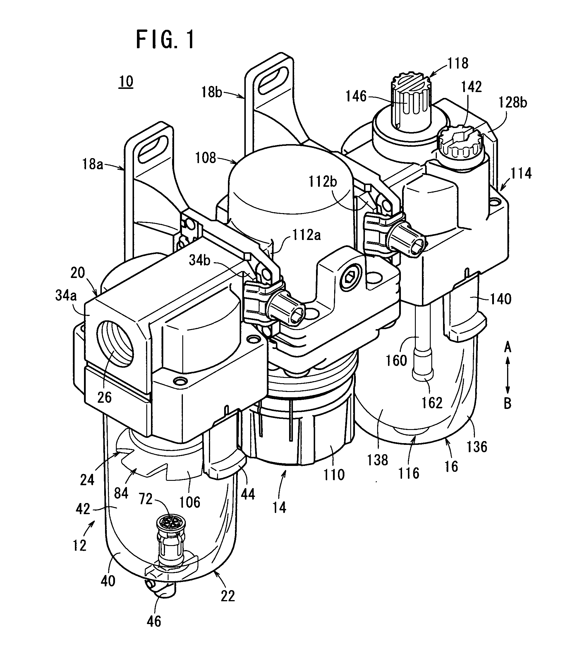
[0030]In FIG. 1, reference numeral 10 indicates a fluid pressure unit including a filter apparatus according to the present invention.

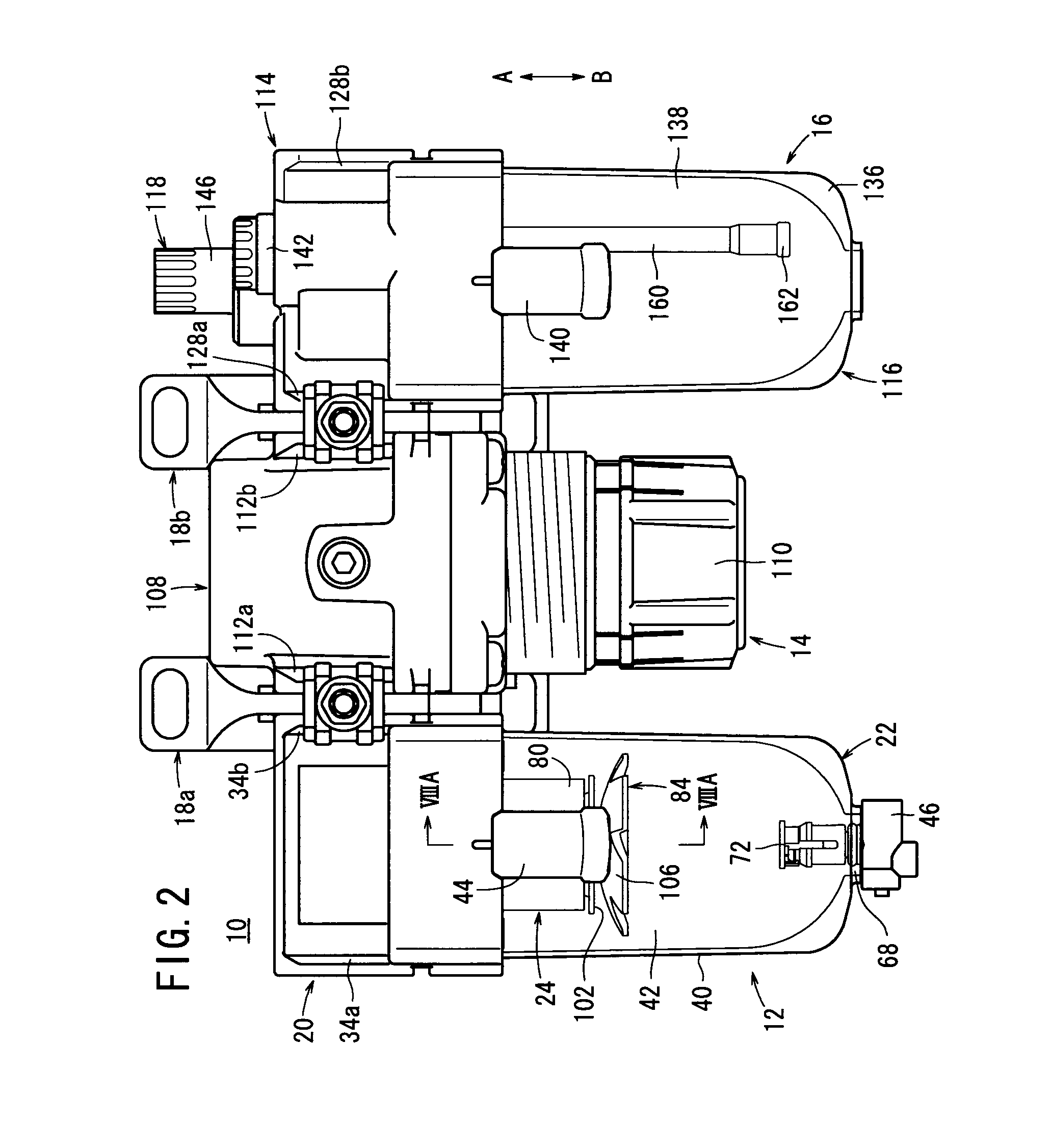
[0031]As shown in FIGS. 1 and 2, the fluid pressure unit 10 is made up from a filter apparatus 12 that removes dust, particulates and the like contained within the pressure fluid, a regulator 14 that reduces the pressure of the pressure fluid, a lubricator 16 that mixes a lubricating oil with respect to the pressure fluid, and connectors 18a, 18b that connect the filter apparatus 12, the regulator 14, and the lubricator 16 together mutually.

[0032]The aforementioned filter apparatus 12, the regulator 14, and the lubricator 16 function as fluid pressure devices to which a pressure fluid is supplied to the interiors thereof. The regulator 14 is disposed between the filter apparatus 12 and the lubricator 16.

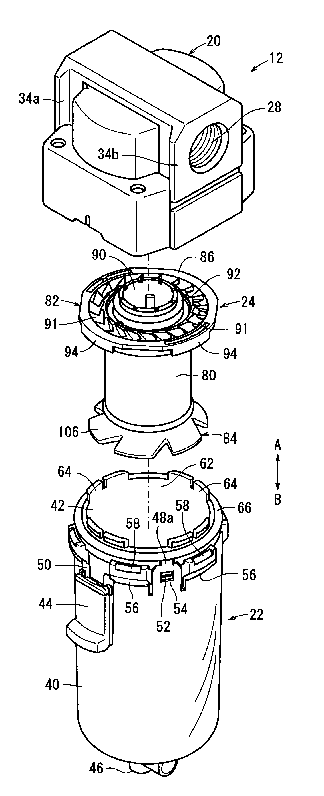
[0033]As shown in FIGS. 1 to 7, the filter apparatus 12 includes a first body (body) 20, a case unit (case) 22 connected to a lower part of the first ...

second embodiment

[0130]Next, explanations shall be made concerning operations and advantageous effects of the fluid pressure unit 200 according to the It is assumed that a desired pressure has been set beforehand by operating the handle 214.

[0131]First, the pressure fluid is supplied from a non-illustrated pressure fluid supply source to the fifth port 216 of the body 204. The pressure fluid flows to the interior of the inner case 226 by passing through the fifth communication passage 220, and is guided downward while undergoing rotation by passing between the fins 91 of the deflector 82. On this occasion, moisture and the like contained within the pressure fluid are suitably separated out due to centrifugal force caused by such rotation, and the pressure fluid moves toward the inner circumferential side of the inner case 226.

[0132]Further, the separated moisture, after moving downward along the inner circumferential surface of the inner case 226, collects as moisture to be drained in the bottom of...


PUM

PropertyMeasurementUnit
pressureaaaaaaaaaa
shapeaaaaaaaaaa
displacementaaaaaaaaaa

Abstract

A filter apparatus (12) is equipped with a first body (20), a case unit (22) connected to a lower part of the first body (20), and a filter unit (24), which is accommodated in the interior of the case unit (22). The case unit (22) is made up from an outer case (40), which is formed as a bottomed cylinder from a light-permeable transparent material, and an inner case (42) that is inserted into the interior of the outer case (40). The case unit (22) is inserted into an installation hole (36) that opens on the lower part of the first body (20), and by rotation thereof, projections (58) and retaining walls (56) provided on an outer circumferential surface of the case unit (22) are made to engage with support members (38) provided in the installation hole (36), to thereby result in a connected state.

Description

TECHNICAL FIELD[0001]The present invention relates to a filter apparatus for removing dust, particulates and the like contained in a fluid.BACKGROUND ART[0002]Heretofore, a filter apparatus has been known for removing dust, particulates and the like contained within a pressure fluid that is supplied to fluid pressure devices. For example, as disclosed in Japanese Laid-Open Patent Publication No. 2008-188489, such a filter apparatus is constituted from a fluid inlet port provided on an upstream side of a fluid pressure device supplied with the pressure fluid, and to which the pressure fluid is supplied, a main body having a fluid outlet port through which the pressure fluid is discharged, a filter element connected to a lower portion of the main body, and a case, which is connected to a lower portion of the main body so as to cover the filter element.[0003]In addition, the pressure fluid, which is supplied to the fluid inlet port, is introduced to the interior of the case and passes ...

Claims


Application Information

Patent Timeline
Patent Type & Authority Applications(United States)
IPC IPC(8): B01D46/00B01D46/24
CPCB01D46/24B01D46/0004B01D46/0005B01D46/0031B01D46/2411B01D46/4254B01D46/003B01D46/88B01D46/42B01D46/00
Inventor YAMASE, NORIHIDEOIKAWA, DAISUKE
Owner SMC CORP
Why Eureka
Try Eureka