
Communication System, Control Method for Electronic Device and Communication System, and Computer-Readable Storage Medium

a technology of communication system and control method, applied in the direction of connection management, machine-to-machine/machine-type communication service, instruments, etc., can solve the problems of difficult to judge which electronic device is connected the electronic device that is a connection candidate and the connection to an unintended electronic device cannot be intuitively recognized

Active Publication Date: 2016-10-06
CASIO COMPUTER CO LTD
View PDF5 Cites 5 Cited by
  • Summary
  • Abstract
  • Description
  • Claims
  • Application Information

AI Technical Summary

Benefits of technology

The patent describes a communication system and method for controlling electronic devices that allows for easy and reliable connection when using wireless communication for information transfer. The invention also includes a computer-readable storage medium for this purpose.

Problems solved by technology

However, with the displayed technical information list alone, the electronic devices that are connection candidates cannot be intuitively recognized.
Moreover, when similar pieces of information regarding a plurality of electronic devices are displayed in a list form, it is difficult to judge which electronic device is to be selected as a connection target, and an erroneous selection may be made.
As a result, connection to an unintended electronic device may be made, or connection may not be established.

Method used


Image

  • Communication System, Control Method for Electronic Device and Communication System, and Computer-Readable Storage Medium
  • Communication System, Control Method for Electronic Device and Communication System, and Computer-Readable Storage Medium
  • Communication System, Control Method for Electronic Device and Communication System, and Computer-Readable Storage Medium

Examples


first embodiment

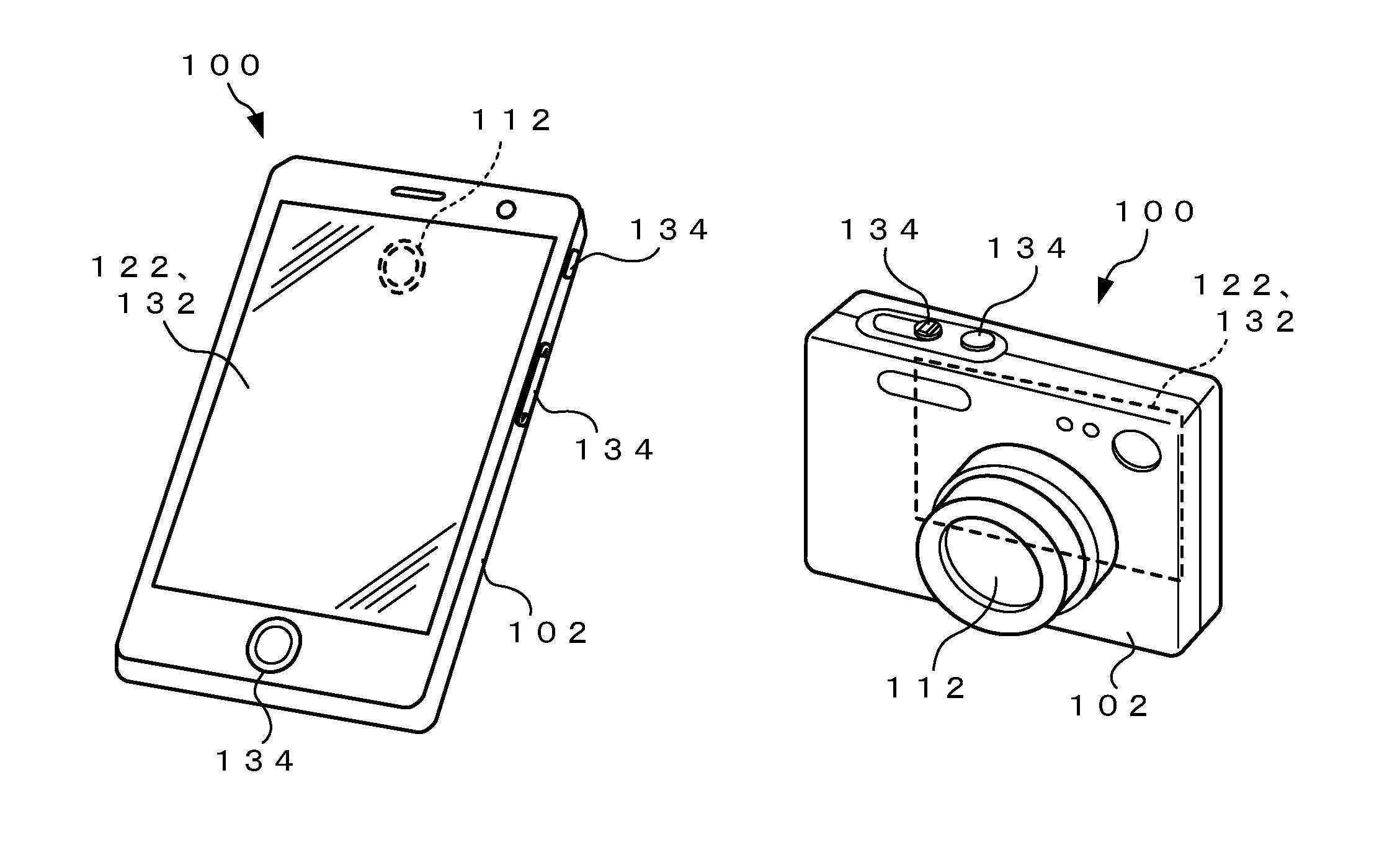
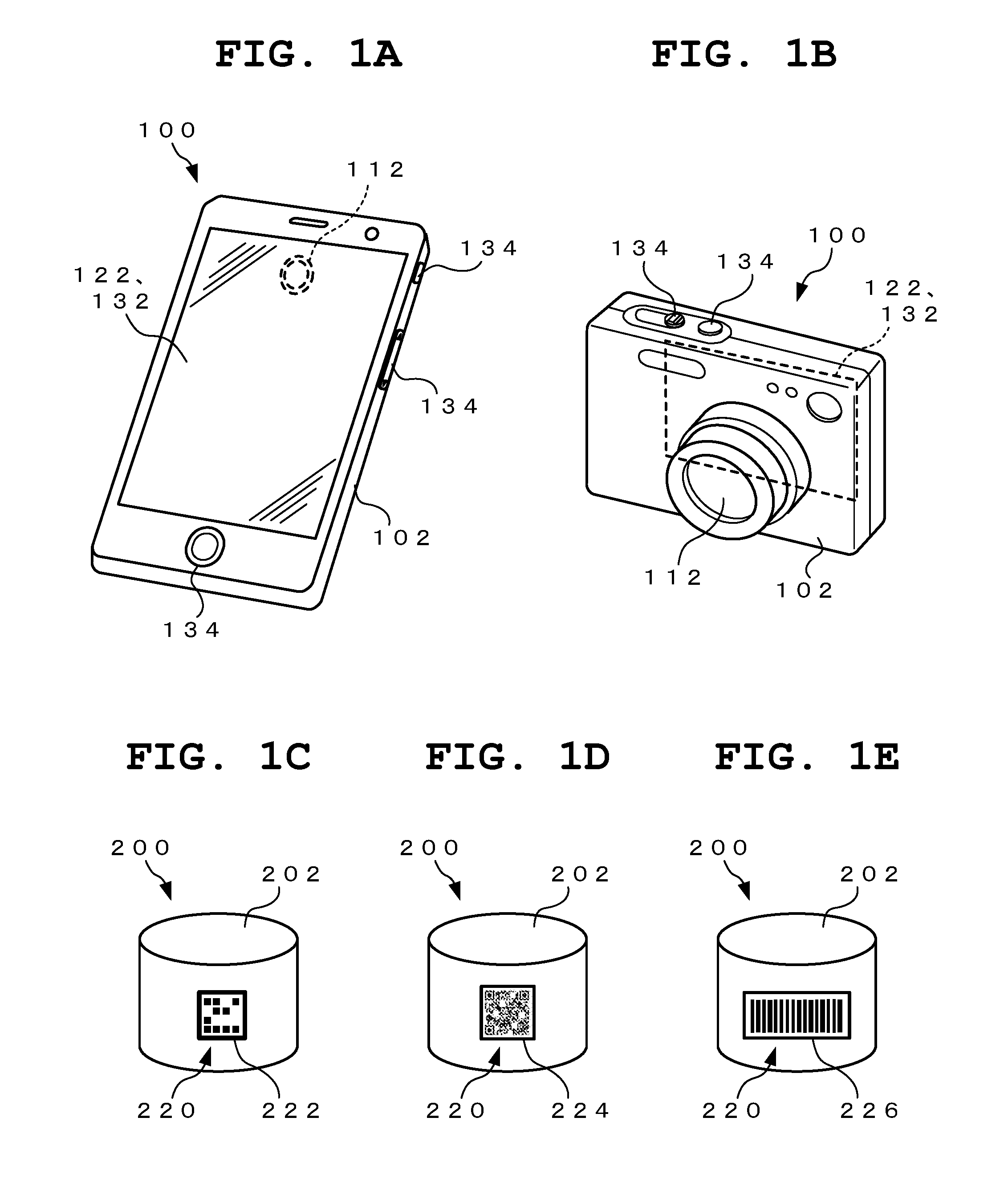
[0026]FIG. 1A to FIG. 1E are schematic structural diagrams showing a first embodiment of a communication system according to the present invention, of which FIG. 1A and FIG. 1B are schematic views showing examples of a portable-electronic device according to the present embodiment (hereinafter referred to as “portable device” for convenience of explanation), and FIG. 1C to FIG. 1E are schematic views showing examples of an electronic device serving as a connection target according to the present embodiment (hereinafter referred to as “target device” for convenience of explanation).

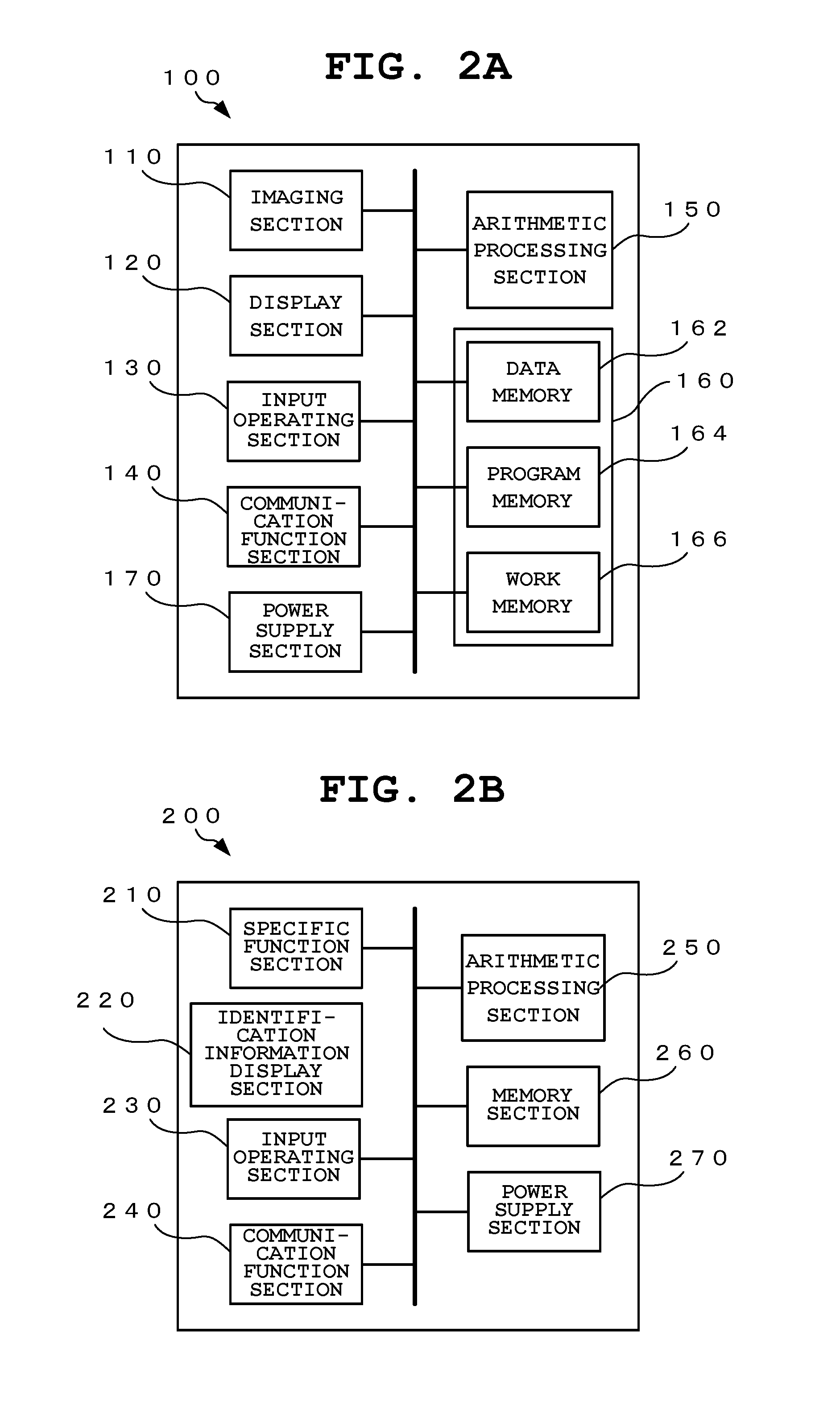
[0027]FIG. 2A and FIG. 2B are block diagrams showing examples of the functional structures of a portable device and a target device that are applied in the first embodiment, of which FIG. 2A is a block diagram showing an example of the functional structure of the portable device, and FIG. 2B is a block diagram showing an example of the functional structure of the target device.

[0028]The communication syste...

second embodiment

[0134]Next, a second embodiment of the communication system according to the present invention is described with reference to the drawings.

[0135]FIG. 7A and FIG. 7B are schematic structural diagrams of the second embodiment of the communication system according to the present invention.

[0136]FIG. 8 is a block diagram showing an example of the functional structure of a target device applied in the present embodiment.

[0137]Note that sections equivalent to those of the above-described first embodiment are provided with the same reference numerals and descriptions thereof are simplified.

[0138]In the above-described first embodiment, the structure has been described in which the identification image presentation section 220 having the identifier 222, 224, or 226 formed of an AR marker, QR code (registered trade mark), or the like is provided on the outer surface of the housing of each target device.

[0139]A feature of the second embodiment is that the identification image presentation sec...


PUM


Abstract

A communication system includes a first electronic device and at least one second electronic device. The second electronic device has a communication function section having a function for performing communication and an identification image presentation section which provides, at a position that can be captured from outside, an identification image having device information including the type of a communication standard for the communication to be performed by the communication function section. The first electronic device has a control section and a display section, and the control section acquires the device information from a captured image of the identification image, and causes a combination image that is a combination of an image of the second electronic device and image information correspond to the device information to be displayed on the display section.

Description

CROSS-REFERENCE TO RELATED APPLICATION[0001]This application is based upon and claims the benefit of priority from the prior Japanese Patent Application No. 2015-068216, filed Mar. 30, 2015, the entire contents of which are incorporated herein by reference.BACKGROUND OF THE INVENTION[0002]1. Field of the Invention[0003]The present invention relates to a communication system for the transmission and reception of information and data between electronic devices positioned relatively close to each other, such as wireless LAN communication or Bluetooth communication, a control method for an electronic device and a communication system, and a computer-readable storage medium.[0004]2. Description of the Related Art[0005]In recent years, portable electronic devices such as smartphones (high-functionality portable telephones) and tablet terminals having functions conforming to short-distance wireless communication standards such as wireless LAN (Local Area Network) and Bluetooth (registered ...

Claims


Application Information

Patent Timeline
Patent Type & Authority Applications(United States)
IPC IPC(8): H04W76/02G06K7/14G06F3/048G06F3/0481G06F3/0488
CPCH04W76/021G06K7/1447H04W76/025H04W4/70H04W76/14H04W12/00
Inventor KOROKU, TAISUKE
Owner CASIO COMPUTER CO LTD
Learn More