Reduced compression height piston and piston assembly therewith and methods of construction thereof

a compression height and piston technology, applied in the direction of trunk pistons, machines/engines, plungers, etc., can solve the problems of limiting the degree to which the compression height, the overall engine size, and the compression height can be reduced, so as to achieve the reduction of the compression height and weight of the piston, the compression load is increased, and the compression height (ch) and the compression height of the piston are able to be minimized

Inactive Publication Date: 2014-03-27
TENNECO INC
View PDF13 Cites 23 Cited by
  • Summary
  • Abstract
  • Description
  • Claims
  • Application Information

AI Technical Summary

Benefits of technology

[0007]A piston constructed in accordance with this invention is constructed of steel, thereby providing the piston with enhanced strength and durability to withstand increased compression loads within a cylinder bore, such as those seen in modern high performance engines. Further, due to the novel configuration of the piston, the compression height (CH) and weight of the piston are able to by minimized, thereby allowing an engine in which the pistons are deployed to be made more compact and lightweight.

Problems solved by technology

In order to achieve these goals, the size and compression height of the piston need to be reduced, however, the increased temperature and compression loads within the combustion chamber require maintaining the piston within workable thermal and loading limits.
As such, although desirable to increase the temperature and compression loads within the combustion chamber, there is a tradeoff in that these increases limit the degree to which the compression height, and thus, overall engine size, can be decreased.
Further, the degree to which the weight of the engine can be reduced is compromised in that the increased temperature and load demands placed on the piston require that they be made of steel.

Method used


Image

  • Reduced compression height piston and piston assembly therewith and methods of construction thereof
  • Reduced compression height piston and piston assembly therewith and methods of construction thereof
  • Reduced compression height piston and piston assembly therewith and methods of construction thereof

Examples


Embodiment Construction

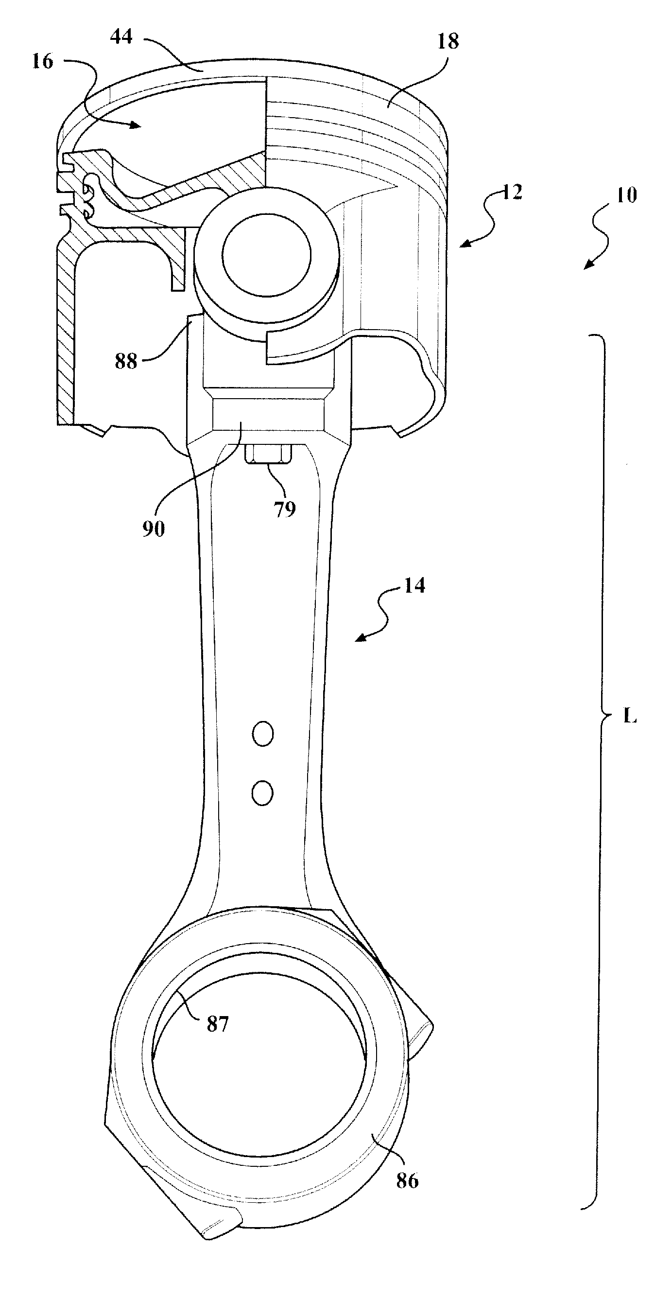
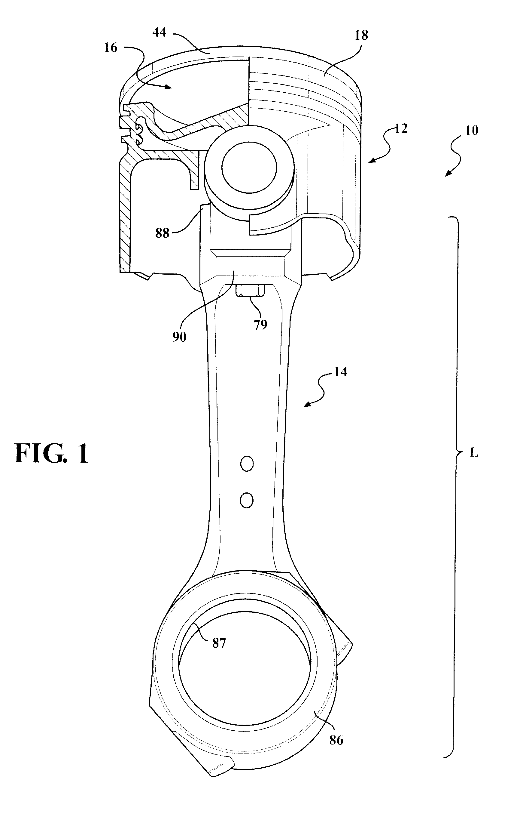
[0069]Referring in more detail to the drawings, FIG. 1 illustrates a partially sectioned perspective view of a piston and connecting rod assembly, referred to hereafter as assembly 10, constructed in accordance with one presently preferred embodiment of the invention, for reciprocating movement in a cylinder bore or chamber (not shown) of an internal combustion engine, such as a modern, compact, high performance vehicle engine, such as a gas or diesel engine for example. The assembly 10 includes a piston 12, a connecting rod 14 and a wrist pin 16. The connecting rod 14 is operably connected to the piston 12 via fixed attachment to the wrist pin 16 for conjoint oscillation with the wrist pin 16. The piston 12 has a body 18 made of at least two separate pieces that are initially fabricated as separate parts and subsequently joined to one another within a head region across some form of a weld joint (i.e., induction weld, friction weld, braze joint, charge carrier rays, laser, resistan...


PUM

PropertyMeasurementUnit
thermal conductivityaaaaaaaaaa
melting temperatureaaaaaaaaaa
particle sizeaaaaaaaaaa

Abstract

A piston assembly and method of construction thereof for an internal combustion engine are provided. The assembly includes a piston head having an upper combustion wall with an undercrown surface and a ring belt region. The piston head has a floor with an upper surface and a bottom surface. The floor is spaced beneath the upper combustion wall in radial alignment with the ring belt region. A substantially enclosed, annular cooling gallery is bounded by the undercrown surface and the floor. A pair of pin bores depends directly from the floor of the cooling gallery. The assembly further includes a pin having ends configured for oscillating receipt in the pin bores. A pin bearing surface extends within the pin bores and between the pin bores in the lower surface of the floor. The assembly includes a connecting rod with an end fixed to the pin for conjoint oscillation therewith.

Description

CROSS-REFERENCE TO RELATED APPLICATIONS[0001]This application claims the benefit of U.S. Provisional Application Ser. Nos. 61 / 706,621, filed Sep. 27, 2012, and 61 / 794,216, filed Mar. 15, 2013, both of which are incorporated herein by reference in their entirety.BACKGROUND OF THE INVENTION[0002]1. Technical Field[0003]This invention relates generally to internal combustion engines, and more particularly to pistons and their method of construction.[0004]2. Related Art[0005]Engine manufacturers are encountering increasing demands to improve engine efficiencies and performance, including, but not limited to, improving fuel economy, improving fuel combustion, reducing oil consumption, increasing the exhaust temperature for subsequent use of the heat within the vehicle, increasing compression loads and temperature within the cylinder bores, decreasing weight and making engines more compact. In order to achieve these goals, the size and compression height of the piston need to be reduced, ...

Claims


Application Information

Patent Timeline
Patent Type & Authority Applications(United States)
IPC IPC(8): F02F3/16
CPCF02F3/16F02F3/00F16J1/005F16J1/09F16J1/16F16J7/00Y10T29/49249Y10T29/49268B23P15/08F02F3/0069F02F2200/00
Inventor AZEVEDO, MIGUELWEINENGER, MICHASEL
Owner TENNECO INC
Why Eureka
Try Eureka