Non-pneumatic tire

a non-pneumatic, tire technology, applied in the direction of high-resiliency wheels, wheels with spade lugs, vehicle components, etc., can solve the problems of reducing machine stability, reducing machine traction, control, stability, etc., to reduce the need for conventional service and improve ride characteristics and quality

Active Publication Date: 2014-03-27
MTD PRODUCTS
View PDF11 Cites 73 Cited by
  • Summary
  • Abstract
  • Description
  • Claims
  • Application Information

AI Technical Summary

Benefits of technology

[0006]The invention provides for a non-pneumatic tire and wheel configuration, herein called “non-pneumatic tire” which can improve ride characteristics and quality, while reducing the need for conventional service and maintenance. Ra...

Problems solved by technology

A puncture of a pneumatic tire could result in loss of machine traction, control, and stability.
A lower spring rate, however, can also reduce machine stability, reduce handling capability and increase rolling resistance due to added radial and lateral deflections.
Higher tire pressures (higher spring rates) can reduce rolling resistance, but traction may be reduced creating a potential loss of control.
Many machine users do not set and maintain their tire pressure properly.
This may result in improper machine orientation, and spatial attitude, thereby creating situations which could result in loss of control or stability.
Pneumatic tires are also susceptible to changes i...

Method used


Image

  • Non-pneumatic tire
  • Non-pneumatic tire
  • Non-pneumatic tire

Examples


examples

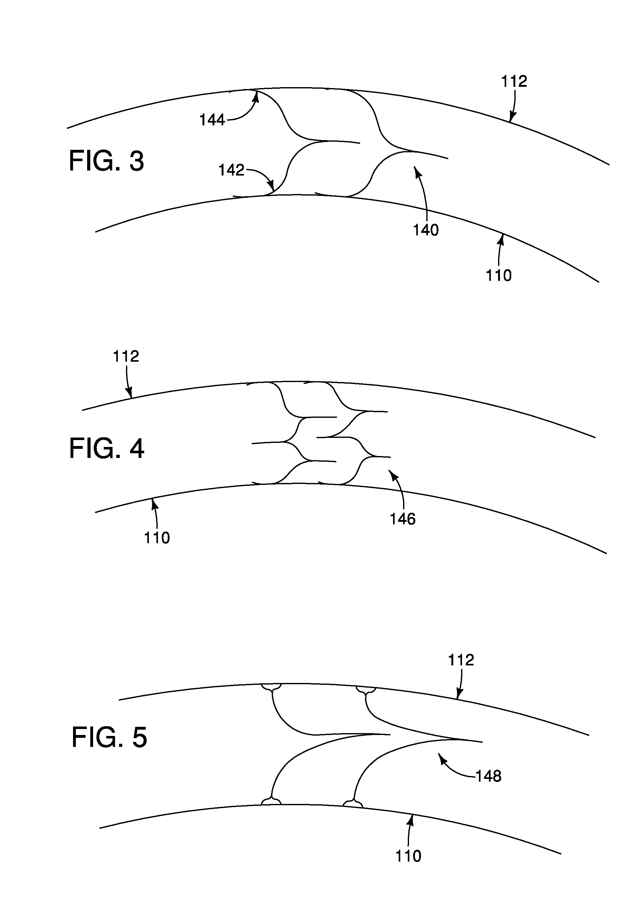
[0052]The assembly stiffness of a non-pneumatic tire wherein the webspokes have generally “Z”-shaped web springs. (“Example 1”) was tested and compared to pneumatic tires (“Comparative Example 1” and “Comparative Example 2”). To measure the assembly stiffness, weights in about 10-lb increments up to 200 lbs. were added at the axis of the central hub. The deflection of the rolling radius was measured at each load. The rolling radius is the radius from the center of the tire axis to the ground. As a load is applied to the central hub, the rolling radius decreases. This decrease in the rolling radius is known as deflection. Stiffer tires will deflect less.

[0053]For the Comparative Examples, the weights were applied to a lawn and garden tractor with pneumatic tires, the tire deflection was measured, and the assembly stiffness was calculated. For Example 1, non-pneumatic tires were placed on the lawn and garden tractor and the same steps were repeated. The assembly stiffness for both the...


PUM


Abstract

A non-pneumatic tire with at least one annular band having an inner ring and a deformable outer ring, a plurality of generally flexible web-spokes connecting the inner ring to the outer ring and a ground contacting tread cap affixed to the annular band.

Description

FIELD OF THE INVENTION[0001]The present invention is directed to a non-pneumatic tire, more particularly, to a non-pneumatic tire for walk-behind or riding lawn, garden, and farm equipment.BACKGROUND OF THE INVENTION[0002]A pneumatic, or air-filled, tire is made of an airtight inner core filled with pressurized air or nitrogen. A tread, usually reinforced with steel belting or other materials, covers this inner core and provides the contact area with the traction surface. The pressure of the air inside the tire is greater than atmospheric air pressure, so that the tire remains inflated even with the weight of a machine resting on it. The air pressure within tires provides a cushioning effect and resistance, sometimes called “air springs”, to radial, lateral, and torsion forces that try to deform the tire as the tire hits bumps and holes. A puncture of a pneumatic tire could result in loss of machine traction, control, and stability.[0003]Pneumatic tires also undergo variances in air...

Claims


Application Information

Patent Timeline
IPC IPC(8): B60B9/02
CPCB60B9/02B60B9/26B60B2900/351B60Y2200/22
Inventor SCHAEDLER, AXELCMICH, RYANPAUSCHE, BRADEAVENSON, SR., JIMMY N.
Owner MTD PRODUCTS
Why Eureka
Try Eureka