
Nanotube dispersants and dispersant free nanotube films therefrom

a technology of nanotubes and nanotubes, which is applied in the direction of non-conductive materials with dispersed conductive materials, mechanical vibration separation, inks, etc., can solve the problems of inability to use high-end electronic applications, irreversible binding of nt dispersants, and inability to form transparent conductive thin-film electrodes, etc., to achieve the effect of improving the conductivity of the film and reducing the apparent transparency of the film

Active Publication Date: 2014-03-27
UNIV OF FLORIDA RES FOUNDATION INC
View PDF0 Cites 32 Cited by
  • Summary
  • Abstract
  • Description
  • Claims
  • Application Information

AI Technical Summary

Benefits of technology

The invention is about a way to make a transparent film with good electrical contact between small conductive parts called NTs. The film is made by depositing the NTs in a specific pattern, like a grid, which creates thin NT windows in between thick NT lines. This pattern makes the film stronger but less transparent, while maintaining good conductivity. Existing methods of making thin films with good electrical contact can be slow and expensive, but this invention offers a way to make a faster and more cost-effective process.

Problems solved by technology

Many dispersants, especially polymeric dispersants, have been designed to blend NTs into polymer composites as reinforcement materials but are not appropriate for the formation of transparent conductive thin-film electrodes.
Typically, NT dispersants are irreversibly bound to the nanotubes, where the NT dispersant exceeds the content of the NTs in the thin film and have not demonstrated the capability for use in high-end electronic applications.

Method used


Image

  • Nanotube dispersants and dispersant free nanotube films therefrom
  • Nanotube dispersants and dispersant free nanotube films therefrom
  • Nanotube dispersants and dispersant free nanotube films therefrom

Examples


Embodiment Construction

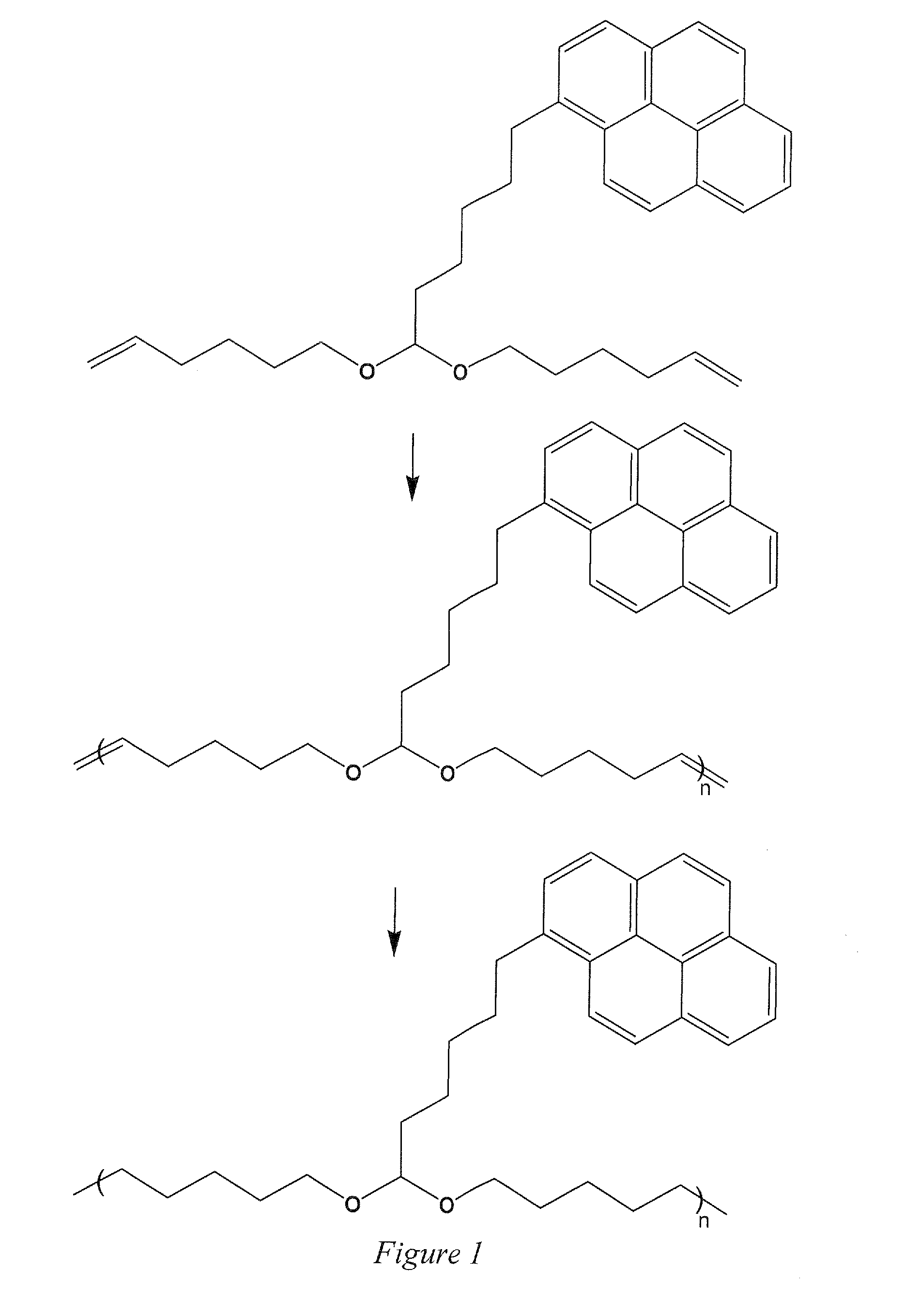
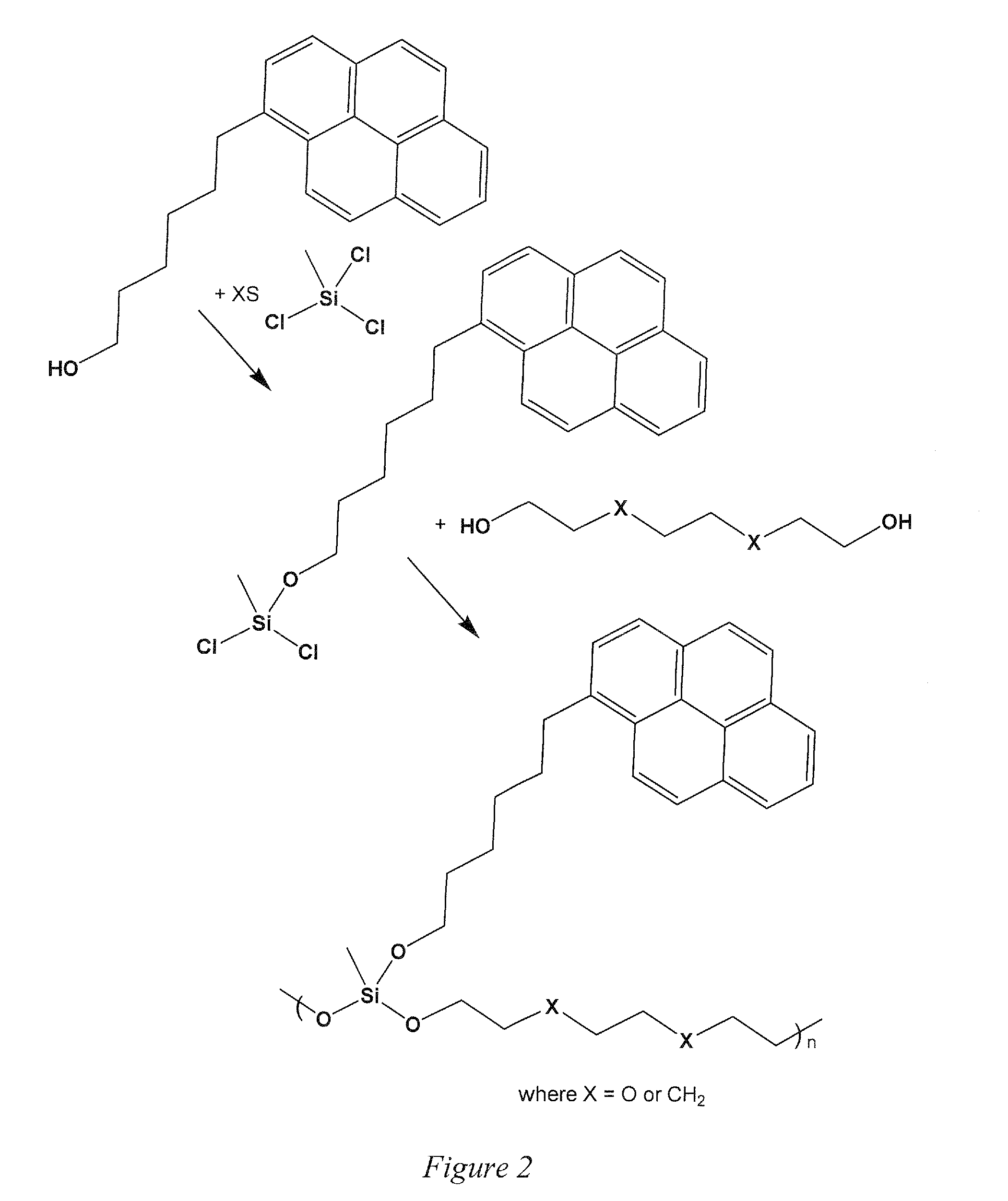
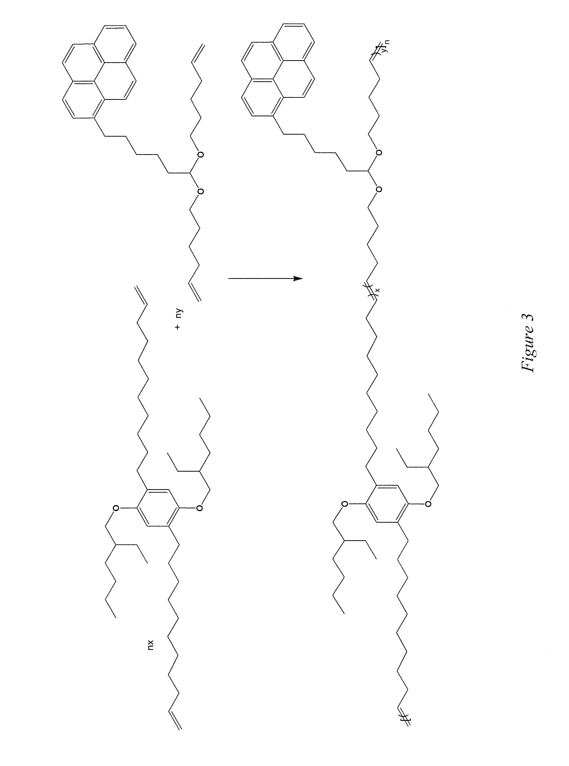
[0018]Embodiments of the invention are directed to an on demand degradable polymeric dispersant for carbon nanotubes (NTs) having a multiplicity of NT associative groups where the dispersant can be removed after formation of a film or other structure by a degradation of the dispersant to individual, monomeric, associative groups that remain after cleavage from the polymer. The associative groups can be polycyclic aromatic units, such as a pyrene units. The NT associative groups bind strongly to the NTs in a cooperative manner when linked via the polymer, where binding of multiple individual NT associative groups keep the NT coupled to the polymers independently of the association or dissociation of any individual NT associative group with the NT. Upon cleavage of cleavable groups, the NT associative groups dissociate from the polymers, allowing the monomeric NT associative groups to undergo an associative / dissociative equilibrium that can be driven to the dissociative form and allow...


PUM

PropertyMeasurementUnit
transmittanceaaaaaaaaaa
transparencyaaaaaaaaaa

Abstract

A degradable polymeric nanotube (NT) dispersant comprises a multiplicity of NT associative groups that are connected to a polymer backbone by a linking group where there are cleavable groups within the polymer backbone and / or the linking groups such that on a directed change of conditions, bond breaking of the cleavable groups results in residues from the degradable polymeric NT dispersant in a manner where the associative groups are uncoupled from other associative groups, rendering the associative groups monomelic in nature. The degradable polymeric nanotube (NT) dispersant can be combined with carbon NTs to form a NT dispersion that can be deposited to form a NT film, or other structure, by air brushing, electrostatic spraying, ultrasonic spraying, ink-jet printing, roll-to-roll coating, or dip coating. The deposition can render a NT film that is of a uniform thickness or is patterned with various thicknesses. Upon deposition of the film, the degradable polymeric nanotube (NT) dispersant can be cleaved and the cleavage residues removed from the film to yield a film where contact between NTs is unencumbered by dispersants, resulting in highly conductive NT films.

Description

CROSS-REFERENCE TO RELATED APPLICATION[0001]The present application claims the benefit of U.S. Provisional Application Ser. No. 61 / 471,582, filed Apr. 4, 2011, which is hereby incorporated by reference herein in its entirety, including any figures, tables, or drawings.BACKGROUND OF INVENTION[0002]Carbon nanotubes (NTs) have received significant attention for technological applications because of their desirable properties, which include high electrical conductivity, high carrier mobility, and high mechanical strength; and due to their ability to be processed into various forms such as fibers and thin films. NTs in the form of networks and films have been proposed as electrodes for several types of devices, including: polymeric supercapacitors; transparent electrodes for organic light emitting diodes and organic photovoltaic devices; and organic electrodes for organic light emitting diodes, organic photovoltaic devices, and organic electrochromic devices. NT dispersions within an ele...

Claims


Application Information

Patent Timeline
Patent Type & Authority Applications(United States)
IPC IPC(8): C09D147/00C09D101/02H05K1/09C09D11/00
CPCC09D147/00H05K1/092C09D101/02C09D11/52C08J3/02C08J2300/10C09D5/027C09D11/30B82Y30/00B82Y40/00C01B32/194C08K3/041C01B32/174C09D7/70C09D7/45C08L1/284C08L101/02C08K3/042C01B32/168B05D1/04B05D1/18B05D1/28B05D3/007C08J5/18C08K7/24C08K9/04C08L101/16C09D101/16H05K2201/0323
Inventor WALCZAK, RYAN M.REYNOLDS, JOHN R.RINZLER, ANDREW GABRIELSPRING, ANDREW M.VASILYEVA, SVETLANA V.WADHWA, POOJA
Owner UNIV OF FLORIDA RES FOUNDATION INC
Learn More