VTOL Aircraft with Propeller tiltable around two Axes and a retractable Rotor

a technology of propellers and rotors, which is applied in the direction of rotorcraft, vertical landing/take-off aircraft, vehicles, etc., can solve the problems of high remaining thrust components of lifting and high speed cruising of aircraft, and achieve the effects of reducing weight, space requirements and costs, improving fuel efficiency and flight control, and reducing weight and space requirements

a technology of propellers and rotors, which is applied in the direction of rotorcraft, vertical landing/take-off aircraft, vehicles, etc., can solve the problems of high remaining thrust components of lifting and high speed cruising of aircraft, and achieve the effects of reducing weight, space requirements and costs, improving fuel efficiency and flight control, and reducing weight and space requirements

US20140084114A1Inactive Publication Date: 2014-03-27VALENTIN INGO

Image

  • VTOL Aircraft with Propeller tiltable around two Axes and a retractable Rotor
  • VTOL Aircraft with Propeller tiltable around two Axes and a retractable Rotor
  • VTOL Aircraft with Propeller tiltable around two Axes and a retractable Rotor

Examples


Embodiment Construction

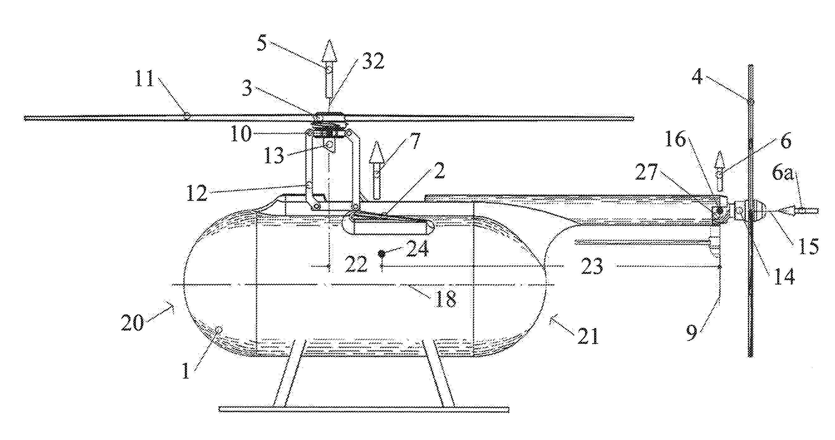
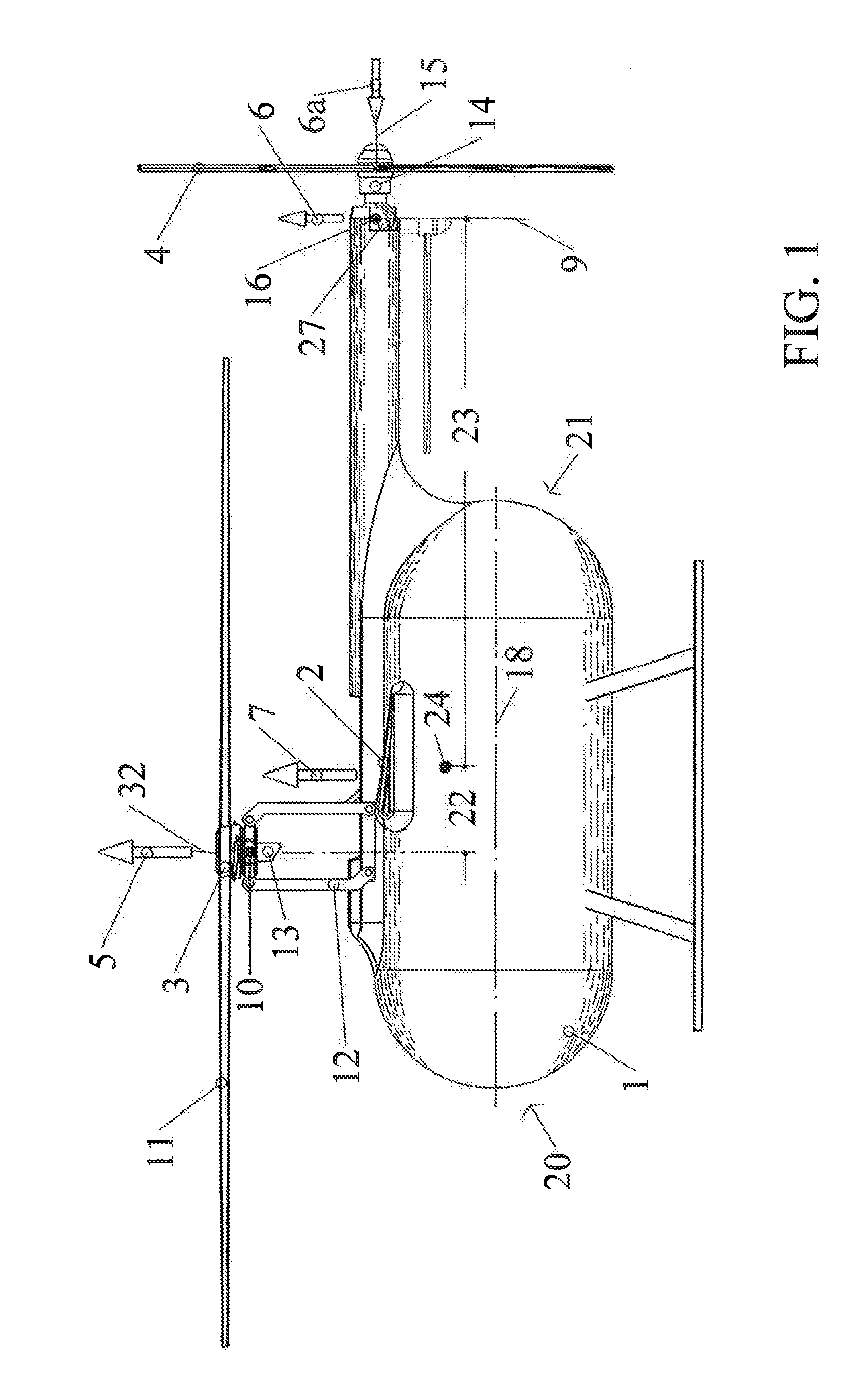
[0034]The aircraft, shown in FIG. 1, consists of fuselage 1, wings 2, at least one rotor assembly 3 and at least one propeller assembly 4 as drive system. Rotor and propeller provide the thrust forces 5 and 6 during vertical take-off and landing (VTOL). During the transition, the propeller, continuously tilting in a horizontal position, provides thrust forces for horizontal flight, and the rotor thrust force 5 are increasingly substituted by the lifting force 7 of the wing. To achieve the VTOL and winged flight capability, the aircraft includes the following new features:

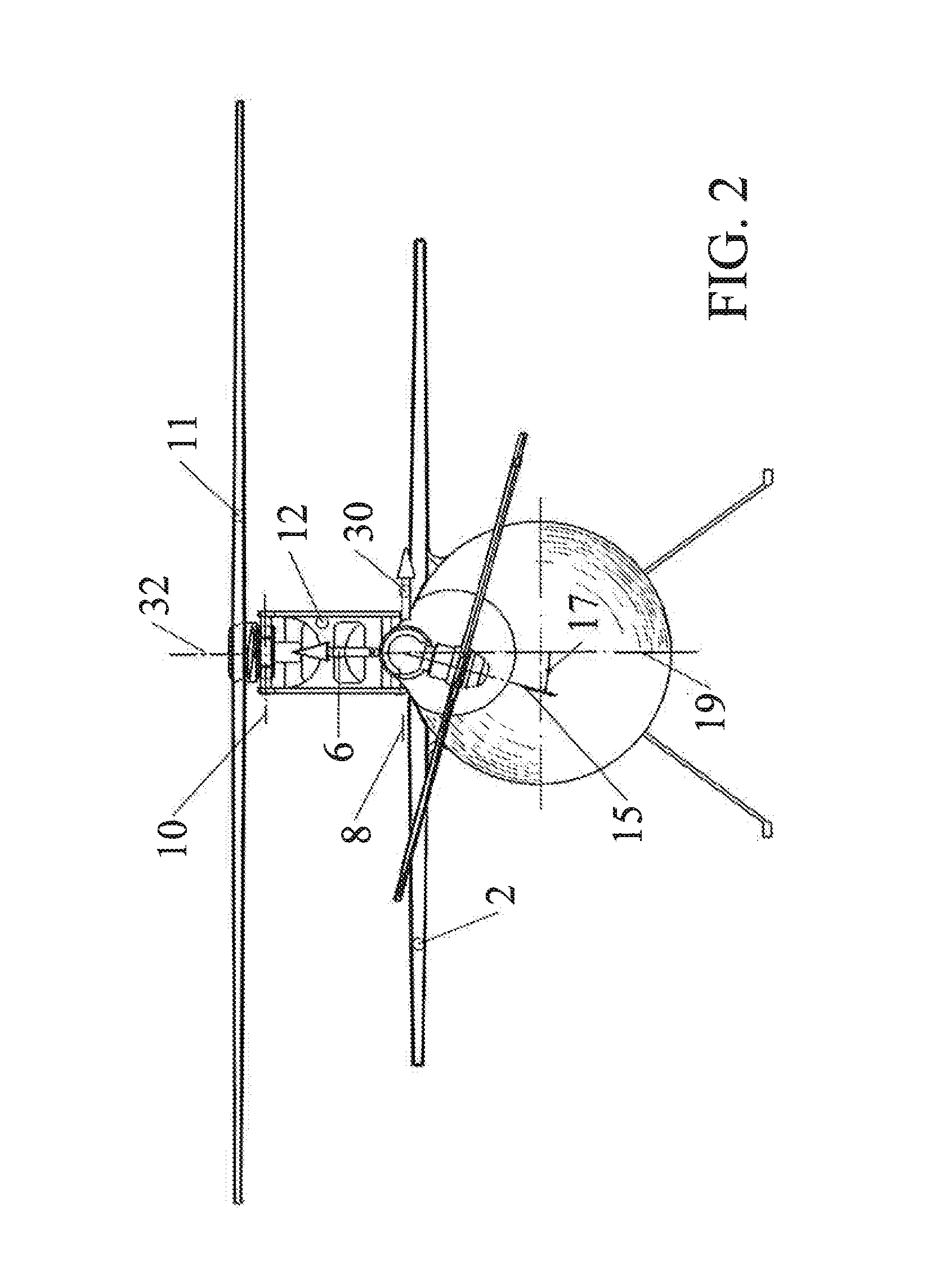
[0035]1. The propeller is tiltable around two axis 8 (FIG. 2) and 9 (FIG. 1) providing the vertical lifting force 6 for VTOL and thrust force 6a for horizontal flight, and to provide a thrust force in horizontal direction for countering the moment of the rotor.

[0036]2. Rotor assembly 3 is tiltable around at least one axis 10 (FIG. 2) improving the trimming maneuverability, and auto gyro conditions of the aircraft.

[0...


PUM


Abstract

A VTOL aircraft has a rotor, wings, and a propeller providing thrust for take-off and landing and horizontal flight. The propeller, attached through a joint mechanism to the aircraft, is continuously tiltable around to axes, providing the anti-torque forces for the rotor and thrust forces for lifting the aircraft and for horizontal flight. The hubs of rotor blade sets are rotatable to each other for alignment. The rotor assembly, attached to a moveable linkage mechanism, is tiltable in or against the direction of flight and movable towards to or into the fuselage. The folded and retracted rotor reduces the air drag and the high thrust of the propeller increase the speed of winged flight. The flexibility and lower weight of the drive are preferably achieved with an advanced hydrostatic drivetrain.

Description

BACKGROUND OF THE INVENTION[0001]1. Technical Field[0002]The invention relates generally to VTOL aircrafts or helicopters which take-off and land vertically, and in particular to innovations which increase the maximum speed and range of the aircraft, and reduce the weight, size, and complexity of the drive system.[0003]Helicopters, as a specific type of VTOL aircraft, are well known in the art and consist typically of a rotor for lifting the aircraft and a propeller providing the counter moment for the rotor. A forward tilting of the helicopter results in a horizontal component of the rotor force, providing the thrust for horizontal flight. Although highly advantageous for various applications, helicopters have a very limited speed and travel range, high fuel consumption and low payloads, and are mechanically complex and costly. The speed is limited by the velocity of the tip of the rotor blade turning in the flight direction, where the circumferential velocity of the rotor and the ...

Claims


Application Information

Patent Timeline
27 Mar 2014
Publication
US20140084114A1
IPC
B64C27/30; B64C27/26; B64C27/28; B64C29/00
CPC
B64C27/30; B64C27/28; B64C27/26; B64C29/0016
Inventors
VALENTIN, INGO