Generator rotor, assembly method and related insertion tool

a technology of insertion tool and rotor, which is applied in the direction of electric generator control, magnetic circuit rotating parts, magnetic circuit shape/form/construction, etc., can solve the problems of cumbersome manufacturing process and high maintenance cost, and achieve easy extraction (and introduction), reduce thermal dissipation, and facilitate manufacturing/machine

Active Publication Date: 2014-03-27
GE RENEWABLE TECH WIND BV
View PDF13 Cites 7 Cited by
  • Summary
  • Abstract
  • Description
  • Claims
  • Application Information

AI Technical Summary

Benefits of technology

[0011]In some embodiments, the anchors may be substantially T-shaped with a corresponding groove in the permanent magnet modules. T-shaped anchors and square grooves may rather easily be manufactured / machined.
[0012]In order to securely fasten the magnets to the generator rotor, the permanent magnet modules may comprise one or more belts that are attached to the front and rear of the base element for binding the permanent magnets to the base. Also, the permanent magnets may be covered with a non-magnetic material, such as a resin or stainless steel. A cover may serve to protect the magnets against corrosion, whereas a cover may induce parasitic currents and / or decrease thermal dissipation.
[0013]In some embodiments, the permanent magnet modules may have a length substantially corresponding to half of the length of the generator. Two permanent magnet modules may be inserted behind each other. In these embodiments, one of the modules may be easily extracted (and introduced) from the front of the rotor, and the other module may be easily extracted (and introduced) from the rear, for example during maintenance.

Problems solved by technology

It will be clear that this manufacturing process can be cumbersome.
Furthermore, if one or more magnets is damaged and needs to be replaced, the access to these magnets can be complicated (especially with large size generators), such that maintenance can become very expensive.

Method used


Image

  • Generator rotor, assembly method and related insertion tool
  • Generator rotor, assembly method and related insertion tool
  • Generator rotor, assembly method and related insertion tool

Examples


Embodiment Construction

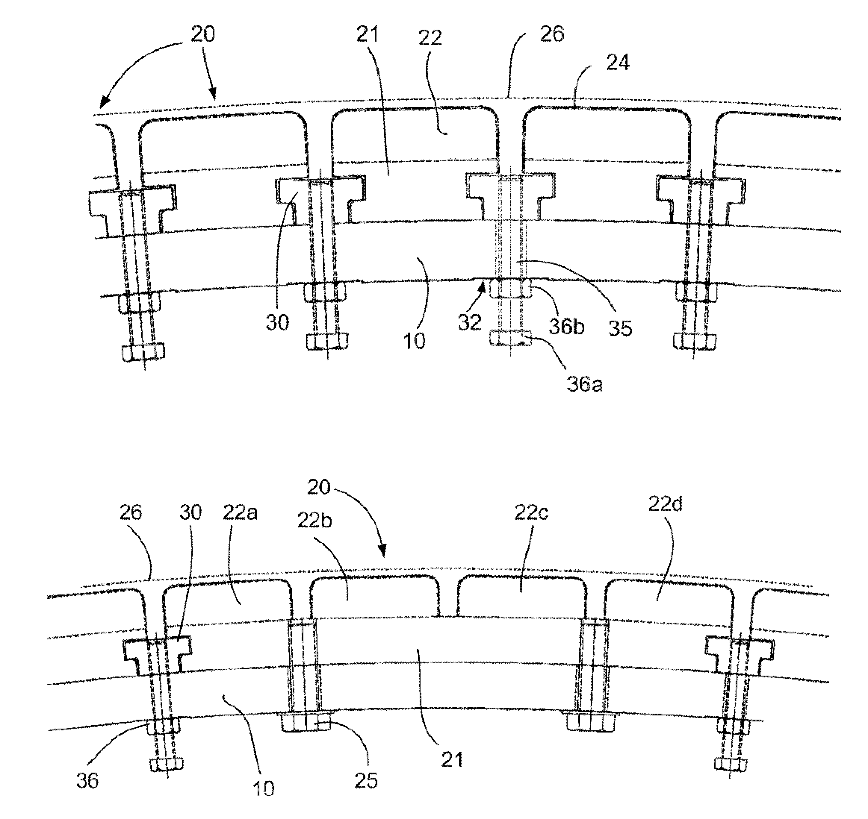
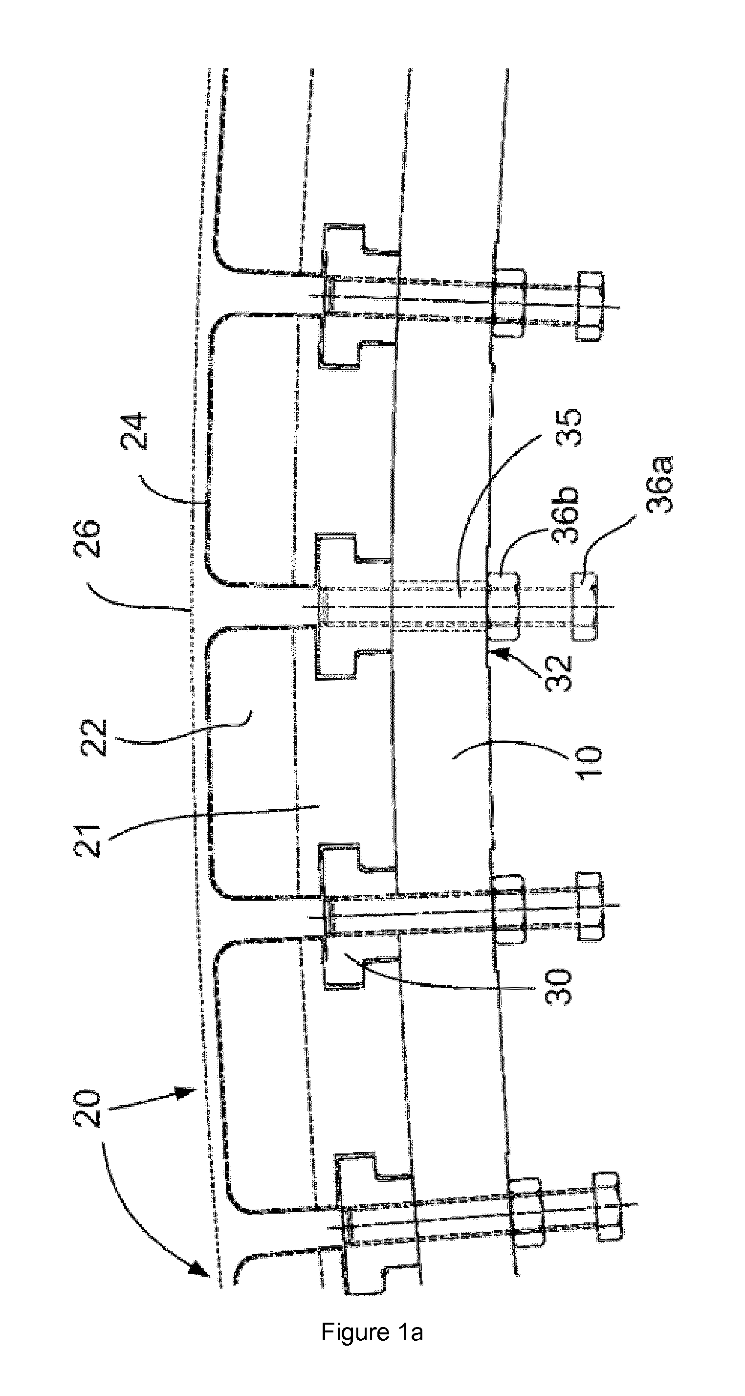
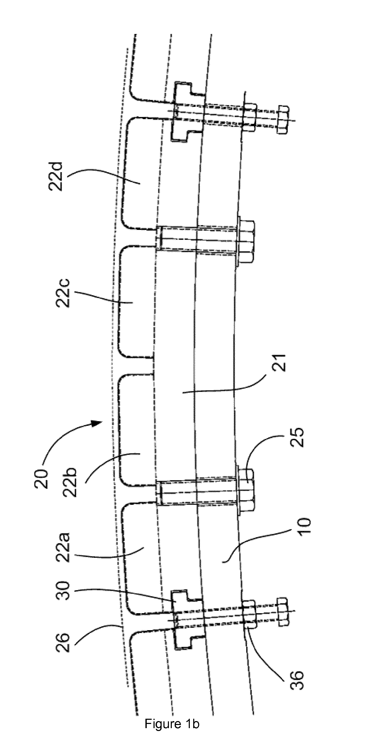
[0025]FIG. 1a illustrates a cross-sectional view of a circle sector of a generator rotor according to an embodiment of the present invention. The generator rotor comprises a rotor rim 10 upon which a plurality of permanent magnet modules 20 is arranged. The permanent magnet modules (and the generator rotor itself) extend in an axial direction from the front to the rear of the generator rotor.

[0026]In this example, the generator comprises a generator stator arranged externally to the generator rotor. The permanent magnet modules are thus arranged on an outer circumference of the rotor rim.

[0027]Each of the permanent magnet modules comprises a base 21 that carries a plurality of magnets 22. In this example, a single row of magnets 22 extending in an axial direction is provided. The side surfaces of the bases 21 comprise a groove in which anchors 30 fit. The base 21 may e.g. be made from steel or another magnetically conducting material and may be made e.g. from one integral piece or f...


PUM

PropertyMeasurementUnit
circumferenceaaaaaaaaaa
shapeaaaaaaaaaa
non-magneticaaaaaaaaaa

Abstract

Generator rotor comprising a rotor rim and a plurality of permanent magnet modules and a plurality of anchors arranged at an outer or inner circumference of the rotor rim such that the anchors substantially fix the permanent magnet modules to the rotor, wherein the permanent magnet modules comprise a base having a bottom surface, two axially extending side surfaces and a top surface, and one or more rows of magnets mounted on said top surface, wherein the two side surfaces of the permanent magnet modules each comprise an axially extending groove, and wherein the anchors have a shape that substantially fits exactly in axially extending grooves of neighbouring permanent magnet modules.

Description

[0001]This application claims the benefit of European Patent Application EP11382142 filed on 11 May 2011 and U.S. Provisional Patent Application Ser. No. 61 / 540,844 filed on 29 Sep. 2011.[0002]The present invention relates to a generator rotor, and more particularly relates to a generator rotor that is especially suitable for a wind turbine.BACKGROUND ART[0003]Generators having a rotor carrying permanent magnets are known. They are generally deemed to be reliable and require less maintenance than other generator topologies.[0004]Modern wind turbines are commonly used to supply electricity into the electrical grid. Wind turbines of this kind generally comprise a rotor with a rotor hub and a plurality of blades. The rotor is set into rotation under the influence of the wind on the blades. The rotation of the rotor shaft either directly drives the generator rotor (“directly driven”) or through the use of a gearbox. For offshore wind turbines, direct drive systems employing permanent ma...

Claims


Application Information

Patent Timeline
Patent Type & Authority Applications(United States)
IPC IPC(8): H02K1/27F03D9/00H02K15/03
CPCH02K1/27F03D9/002H02K15/03H02K1/278H02K7/1838H02K2213/12F03D9/25Y10T29/53143Y10T29/49012Y02E10/72F03D15/20H05K999/99
Inventor MUNIZ CASAIS, CESARCLARAMUNT ESTECHA, SANTIAGO
Owner GE RENEWABLE TECH WIND BV
Why Eureka
Try Eureka