Eureka AIR delivers breakthrough ideas for toughest innovation challenges, trusted by R&D personnel around the world.

Method of dimming backlight assembly

a backlight assembly and backlight technology, applied in the field of backlight assembly dimming, can solve the problems of reducing the crystal display panel may not display a black image, and the light leakage reduce the contrast ratio of the image displayed on the liquid crystal display panel, so as to improve the contrast ratio of the images displayed reduce power consumption in the display panel, and improve display quality

Inactive Publication Date: 2014-03-27
SAMSUNG DISPLAY CO LTD
View PDF8 Cites 6 Cited by
  • Summary
  • Abstract
  • Description
  • Claims
  • Application Information

AI Technical Summary

Benefits of technology

The patent describes a method to improve the quality of images displayed on a display panel while reducing power consumption. This is achieved by determining the representative gray-scale value for the dimming area using a variety of statistical measures, and then using this value to determine the dimming function for the light sources in the area. This results in a higher contrast ratio for the displayed images.

Problems solved by technology

In general, however, the liquid crystal molecules of the liquid crystal layer do not perfectly align, so light leakage occurs in the liquid crystal display panel for low gray-scale values.
That is, although a liquid crystal display panel can display an image at low gray-scale values, the liquid crystal display panel may not display a black image due to light leakage when the backlight unit provides a high intensity light to the liquid crystal display panel.
Accordingly, light leakage reduces the contrast ratio of the image displayed on the liquid crystal display panel.
In addition, in view of energy utilization efficiency, it is inefficient to consume more energy to increase light intensity and then block the light in the liquid crystal display panel.

Method used

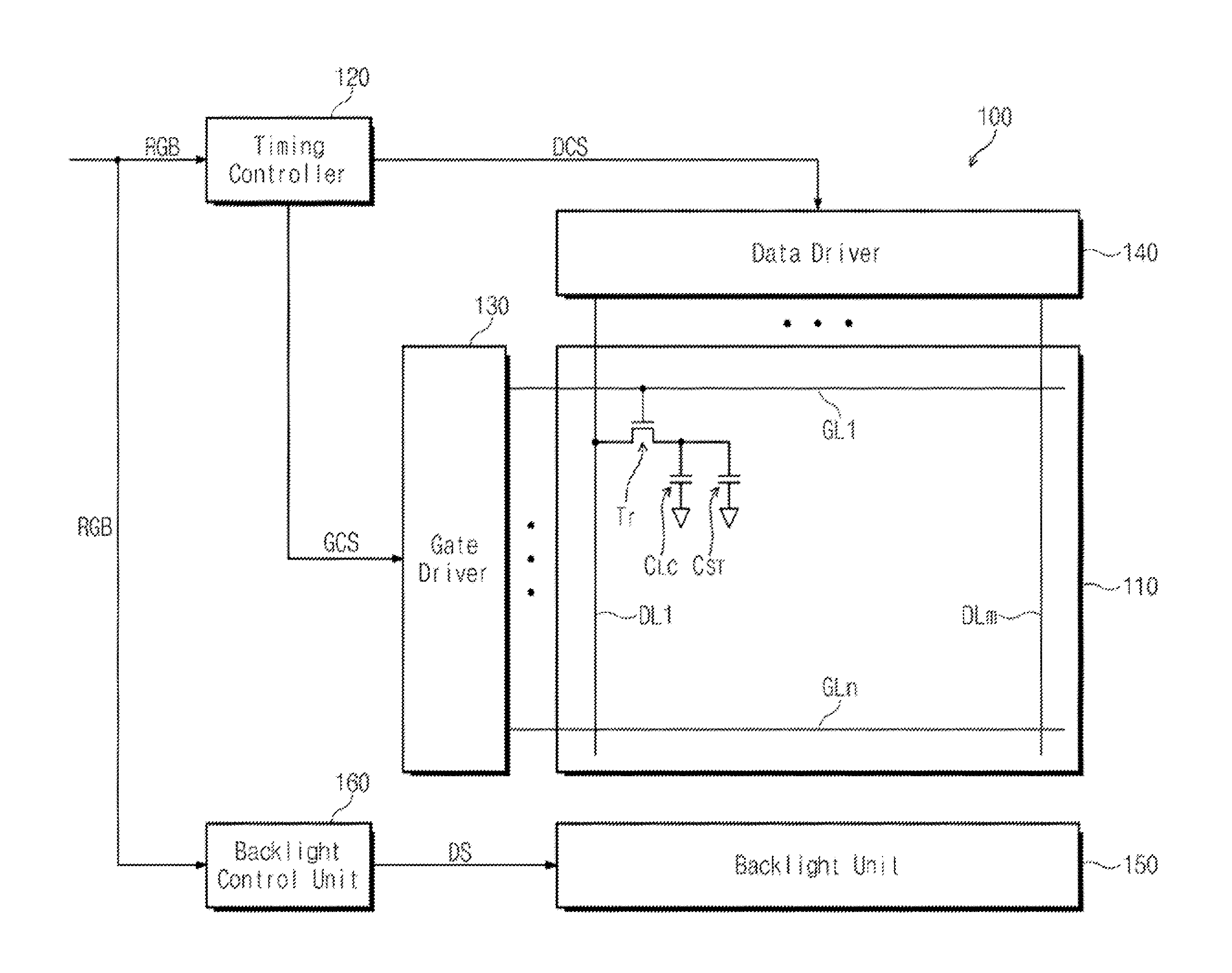
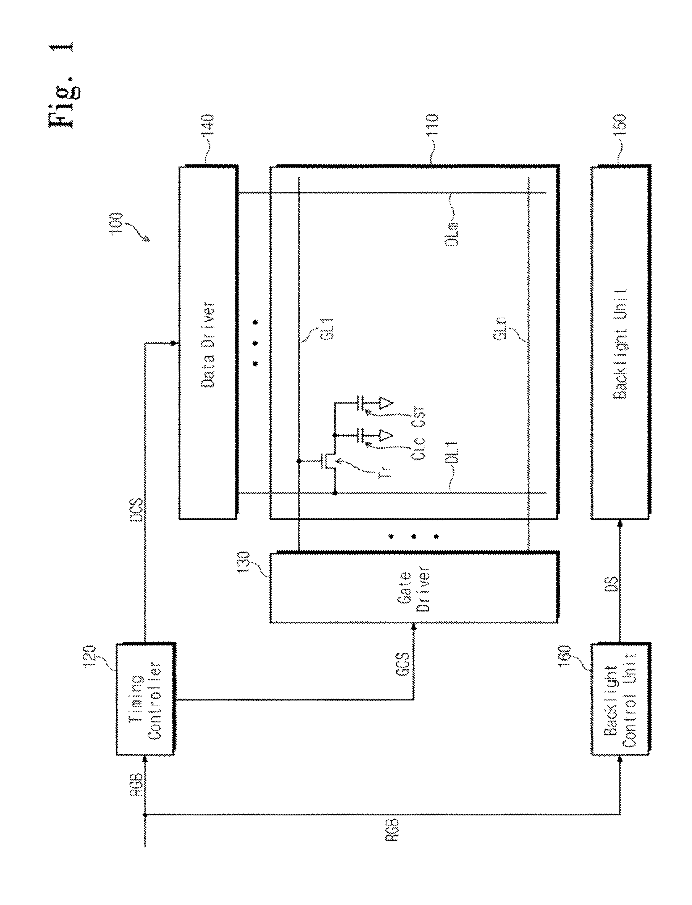
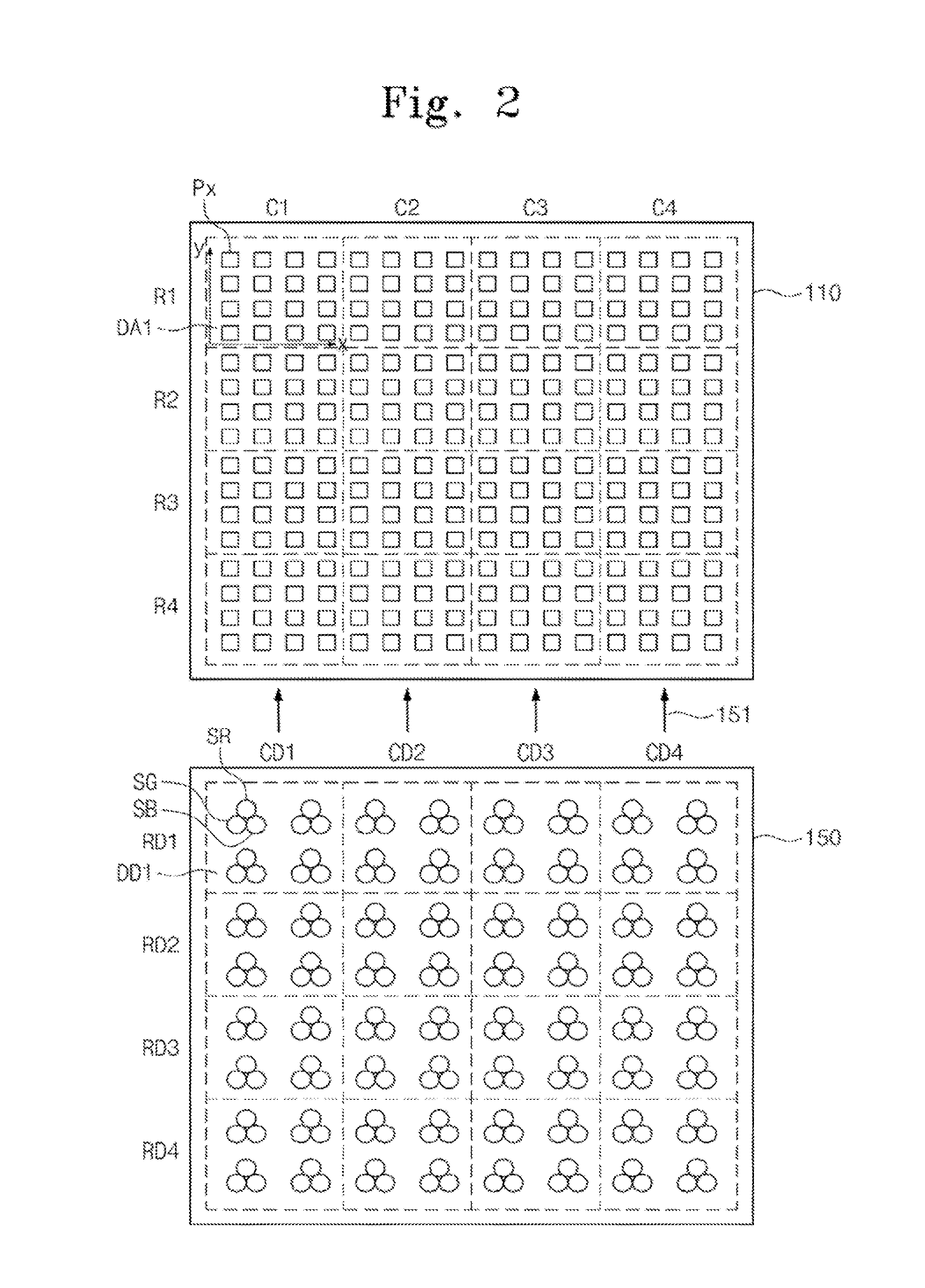

Image

  • Method of dimming backlight assembly
  • Method of dimming backlight assembly
  • Method of dimming backlight assembly

Examples


example 1

[0054]

γ2≧0,GRE=α×m+(1−α)×P,

γ2,GRE=α×m+(1−α)×P

[0055]In Example 1, in denotes the mean value, P denotes the maximum value, γ1 denotes the kurtosis, γ2 denotes the skewness,

α=1C+K

and β are predetermined experimental constants. C is a predetermined constant satisfying the condition 0.5≦C≦1.5. If Max(√{square root over (|μ20|)}, √{square root over (|μ02|)}, {square root over (|μ12|)}, {square root over (|μ21|)}, {square root over (|μ30|)}, {square root over (|μ03|)})≧T, K is Max(| x|, | y|, √{square root over (|μ11|)}). If Max(√{square root over (|μ20|)}, √{square root over (|μ02|)}, {square root over (|μ12|)}, {square root over (|μ21|)}, {square root over (|μ30|)}, {square root over (|μ03|)})ij denotes the central image moment of the i-th degree along the x-axis and of the j-th degree along the y-axis.

γ1≥0,GRE=m-Kσ+γ22,γ1<0,GRE=m+Kσ+γ22.Example2

[0056]In Example 2, m denotes the mean value, σ denotes variance, γ1 denotes the kurtosis, γ2 denotes the skewness, and K is a predetermine...

example 4

[0058]

A≦T1,GRE=m

A≧T2,GRE=P

[0059]When assuming that A is greater than T1 and less than T2 (T12), if the kurtosis γ1 is greater than zero (γ1>0), the representative gray-scale value GRE satisfies a condition α×m+(1−α)×P, i.e., GRE=α×m+(1−α)×P, and if kurtosis γ1 is equal to or less than zero (γ1≦0) the representative gray-scale value GRE satisfies a condition (1−β)×m+β×P, i.e., GRE=(1−β)×m+β×P.

[0060]In Example 4, A=| x|+| y|+√{square root over (|μ11|)}, x denotes the x-axis average raw image moment of the gray-scale values, y denotes the y-axis average raw image moment of the gray-scale values, denotes the central image moment of the i-th degree along the x-axis and of the j-th degree along the y-axis, m denotes the mean value, P denotes the maximum value, γ1 denotes the kurtosis, T1 and T2 are predetermined experimental threshold values, α=Kγ1γ2, β=−Kγ1γ2, K denotes a predetermined experimental constant, and γ2 denotes the skewness.

[0061]Then, again referring back to FIG. 3, when t...


PUM


Abstract

A plurality of gray-scale values is extracted from image signals corresponding to a dimming area to calculate a mean value of the gray-scale values, and at least one of a variance, a standard deviation, a kurtosis, a skewness, a central moment, and an image moment is calculated using the mean value. Then, a representative gray-scale value corresponding to the dimming area is determined using the calculated values, and a dimming function for the light sources included in the dimming area is determined based on the representative gray-scale value. Then, the light sources included in the dimming area are driven based on the dimming function.

Description

CROSS-REFERENCE TO RELATED APPLICATION[0001]This application is a continuation of, and claims priority from U.S. application Ser. No. 12 / 969,809, filed on Dec. 16, 2010 in the U.S. Patent and Trademark Office, which in turn claims priority under 35 U.S.C. §119 from Korean Patent Application No. 10-2010-0025441 filed on Mar. 22, 2010 in the Korean Intellectual Property Office (KIPO), the contents of which are herein incorporated by reference in their entirety.BACKGROUND[0002]1. Field of the Invention[0003]The present disclosure is directed to a method of dimming a backlight assembly. More particularly, the present disclosure is directed to a method of dimming a backlight assembly including controlling a dimming function of light sources divided into at least one dimming area.[0004]2. Description of the Related Art[0005]A liquid crystal display includes a liquid crystal display panel and a backlight unit. The liquid crystal display includes a first substrate, a second substrate, and a...

Claims


Application Information

Patent Timeline
Patent Type & Authority Applications(United States)
IPC IPC(8): G09G3/36
CPCG09G3/3607G09G3/3413G09G3/3426G09G2320/0626G09G2360/16G09G3/36G09G3/3648
Inventor JUNG, TAE KWONYEO, DONGMINYANG, BYUNGCHOONKWON, YONG-HOON
Owner SAMSUNG DISPLAY CO LTD
Why Eureka
Eureka Blog
Learn More