Backlight and liquid crystal display device

a liquid crystal display and backlight technology, applied in the field of backlight and liquid crystal display devices, can solve the problems of reducing the brightness of the peripheral portion of the liquid crystal display panel compared to that of the central portion, and the brightness of the peripheral portion becomes too low to be able to visually recognize, so as to reduce the brightness at the peripheral portion associated with the change of viewing distan

Inactive Publication Date: 2014-03-27
MITSUBISHI ELECTRIC CORP
View PDF10 Cites 45 Cited by
  • Summary
  • Abstract
  • Description
  • Claims
  • Application Information

AI Technical Summary

Benefits of technology

[0010]In a backlight according to the present invention, a decrease in brightness at a peripheral portion associated with the change of viewing distance can be reduced.

Problems solved by technology

Therefore, when viewed at close range, there has been a problem that brightness at a peripheral portion of the liquid crystal display panel is greatly reduced compared to that at a central portion, depending on the difference of angles into which the liquid crystal display panel is looked.
This tendency becomes prominent as the viewing distance decreases and as the size of the liquid crystal display panel increases, and, in an extreme case, the brightness of the peripheral portion becomes too low to be able to visually recognize.

Method used


Image

  • Backlight and liquid crystal display device
  • Backlight and liquid crystal display device
  • Backlight and liquid crystal display device

Examples


embodiment 1

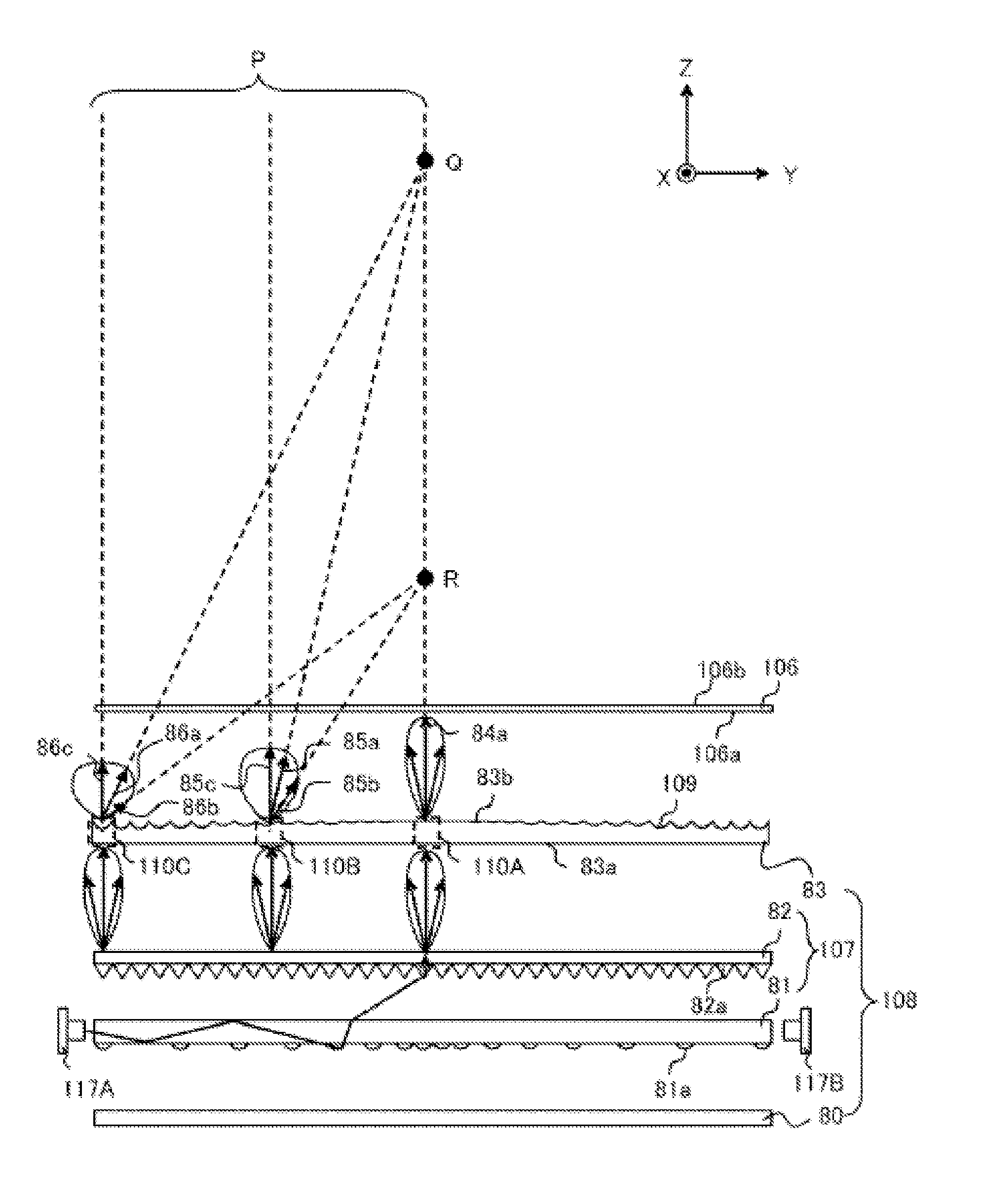
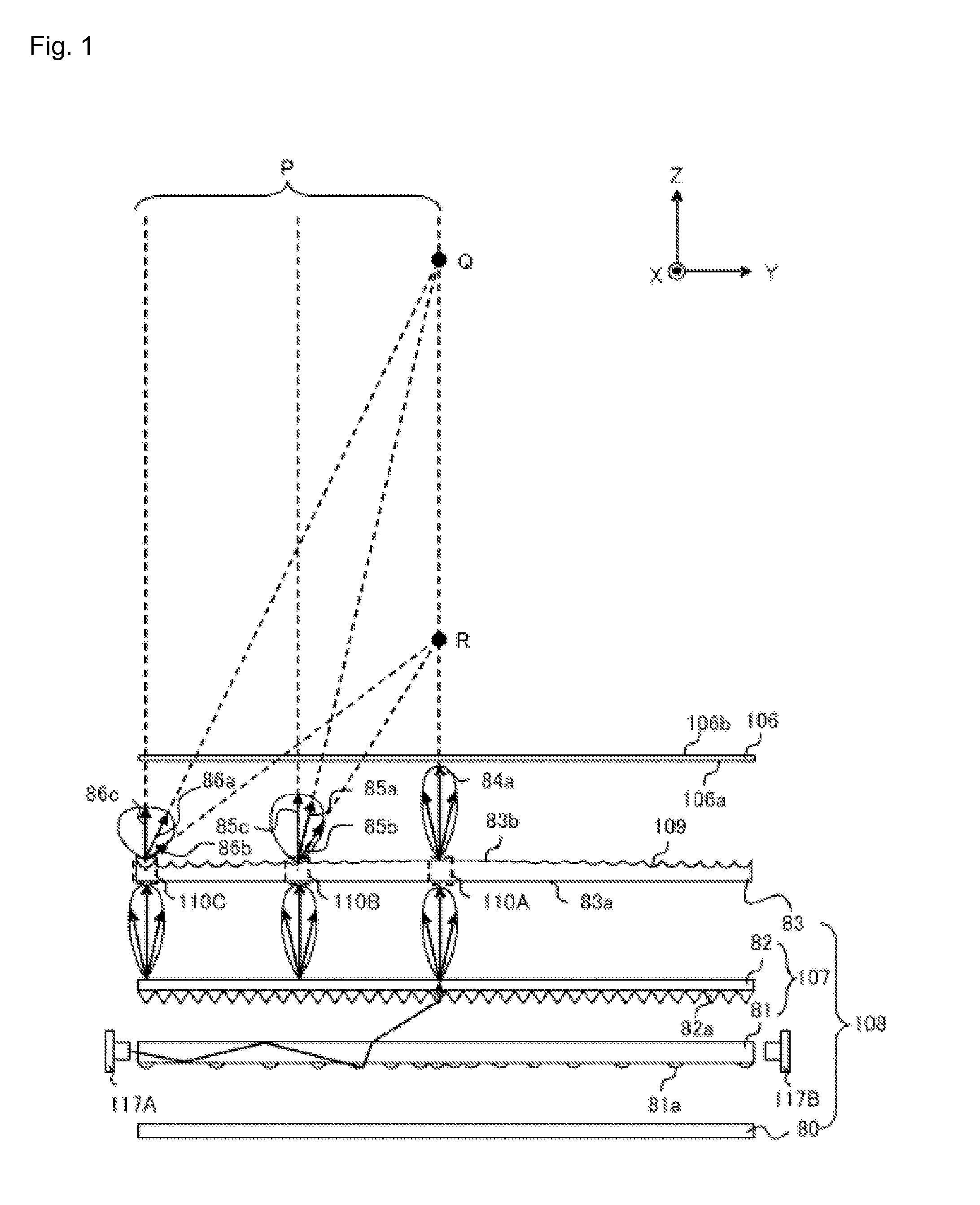
[0043]FIGS. 1 and 2 are diagrams showing a liquid crystal display device in Embodiment 1. FIG. 1 is the diagram schematically showing a configuration of the liquid crystal display device, and FIG. 2 is a perspective view of the liquid crystal display device in FIG. 1.

[0044]As shown in FIGS. 1 and 2, the liquid crystal display device includes a liquid crystal display panel 106 of transmissive type and a backlight 108 for projecting beams toward a rear surface 106a of the liquid crystal display panel 106.

[0045]The liquid crystal display panel 106 has the rear surface 106a and a display surface 106b, and the display surface 106b is provided to be parallel to the X-Y plane that includes the X-axis and Y-axis which are orthogonal to the Z-axis. The normal direction of the display surface 106b is parallel to the Z-axis, and the X-axis and Y-axis are mutually orthogonal.

[0046]The backlight 108 includes a light distribution control member 83, an optical member 107 comprised with a downward ...

embodiment 2

[0073]FIG. 8 is a schematic diagram showing a configuration of a liquid crystal display device in Embodiment 2. In the liquid crystal display device in Embodiment 2, the microscopic optical elements 81a at the rear surface of the light guide plate 81 configuring the optical member 107 are formed so as to be more densely distributed at the peripheral portion than the configuration in Embodiment 1 when the number of elements per unit area is compared. Because the configuration of the liquid crystal display device in Embodiment 2 is similar to that in Embodiment 1, except that the distribution of the microscopic optical elements 81a differs, the explanation thereof will be skipped.

[0074]In a light guide plate of a conventional backlight, it is common that the microscopic optical elements provided at the rear surface of the light guide plate are more sparsely provided as coming close to the light source, while more densely provided as coming close to the central portion so that the plan...

embodiment 3

[0078]FIGS. 9 and 10 show a liquid crystal display device in Embodiment 3. FIG. 9 is a diagram schematically showing a configuration of the liquid crystal display device, and (a) through (c) in FIG. 10 are cross-sectional views enlargedly showing the central, intermediate, and peripheral portions of a light distribution control member in FIG. 9, respectively.

[0079]As shown in FIG. 9, the liquid crystal display device in Embodiment 3 has a configuration in which plural concaves 109 are provided on the light distribution control member 83, similar to that in Embodiment 1. However, while the direction of the peak component of the beams projected from the light distribution control member 83 is parallel to the normal direction of the liquid crystal display panel 106 in Embodiment 1, the difference in Embodiment 3 is that the concaves 109 are slanted against the normal direction of the display surface so that the direction of the peak component of the beams projected from the light distr...


PUM

PropertyMeasurementUnit
refractive indexaaaaaaaaaa
distanceaaaaaaaaaa
heightaaaaaaaaaa

Abstract

An objective is to obtain a backlight in which a decrease in brightness at a peripheral portion associated with the change of viewing distance is reduced. The backlight is comprised with an optical member 107 for transforming beams projected from light sources 117A and 117B into beams having a narrow-angle light distribution in which rays having intensity of no less than a predetermined value are localized within a predetermined angle range centered in the normal direction of a display surface 106b of a liquid crystal display panel 106, and for projecting the transformed beams in the direction of the liquid crystal display panel 106; and a light distribution control member 83 for receiving the beams that are projected from the optical member 107 and that have the narrow-angle light distribution, and for projecting the received beams in the direction of the liquid crystal display panel 106, wherein a plurality of concaves 109 are provided at the light distribution control member 83 for transforming a beam, from among the beams having the narrow-angle light distribution, that enters a peripheral portion of the liquid crystal display panel 106 so that the narrow-angle light distribution of the entered beam is broadened compared to that of a beam that enters a central portion of the liquid crystal display panel 106; and curvature radiuses of the plurality of concaves are formed so that a curvature radius of a concave located at a peripheral portion of the light distribution control member 83 is smaller than a curvature radius of a concave located at a central portion of the light distribution control member 83.

Description

TECHNICAL FIELD[0001]The present invention relates to a backlight used in liquid crystal display devices and a liquid crystal display device equipped with the backlight.BACKGROUND ART[0002]In general, a liquid crystal display device of transmissive type or semi-transmissive type is equipped with a liquid crystal display panel having a liquid crystal layer and a backlight for projecting beams toward a rear surface of the liquid crystal display panel. Previously, a liquid crystal display device of narrow viewing angle type has been proposed, in which an emission beam distribution is narrowed by providing a prism sheet at the beam emission surface side of a light guide plate of the backlight for the purpose of reducing power consumption, increasing brightness, protecting privacy, and the like (for example, see Patent Document 1).[0003]In the above-described liquid crystal display device of narrow viewing angle type, the emission beams projected from a display surface of the liquid crys...

Claims


Application Information

Patent Timeline
Patent Type & Authority Applications(United States)
IPC IPC(8): G02F1/1335F21V8/00
CPCG02B6/005G02F1/133615G02B6/0053G02B6/0061
Inventor KUWATA, MUNEHARUNISHITANI, RENANAKANO, NAMIKOJIMA, KUNIKO
Owner MITSUBISHI ELECTRIC CORP
Why Eureka
Try Eureka