Lighting apparatus

Active Publication Date: 2014-03-27
LG ELECTRONICS INC
View PDF1 Cites 43 Cited by
  • Summary
  • Abstract
  • Description
  • Claims
  • Application Information

AI Technical Summary

Benefits of technology

[0020]As mentioned above, the irradiation angle of the body can be adjusted freely in the lighting apparatus according to the embodiment of the present invention.
[0021]Furthermore, according to the lighting apparatus according to the embodiment, the irradiation angle of the body can be adjusted easily in

Problems solved by technology

The incandescent lamp which is a resistive light source out of such the light sources has disadvantages of deteriorating light emitting efficiency and heat radiation.
The electric discharge lamp has disadvantages of a high price and a high voltage.
The fluorescent lamp has an environmental disadvantage of mercury usage.
Accordingly, a tilted angle of the lamp with respect to the street or the installation surface is unable to be adjusted or the tilted angle of the ins

Method used


Image

  • Lighting apparatus
  • Lighting apparatus
  • Lighting apparatus

Examples


first embodiment

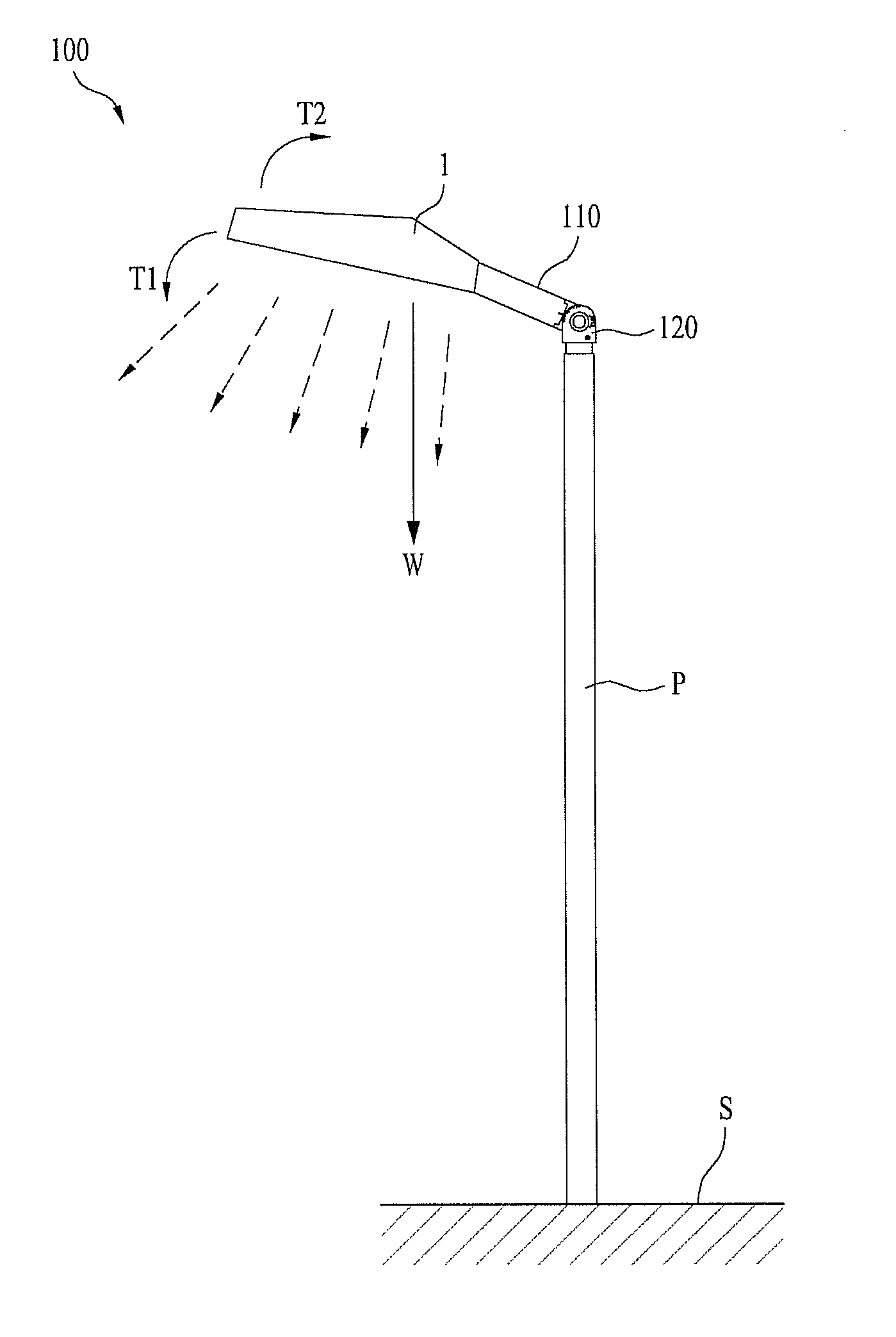
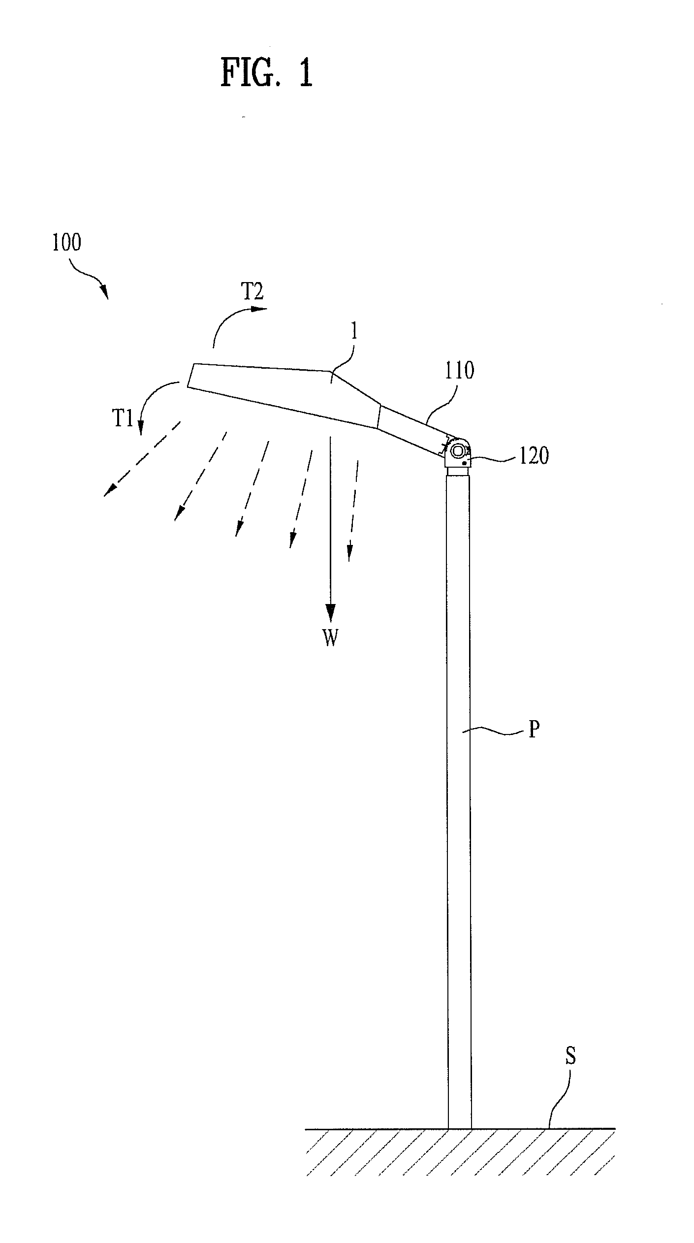
[0046]Referring to the drawings herewith, a lighting apparatus 100 according to the present invention will be described as follows.

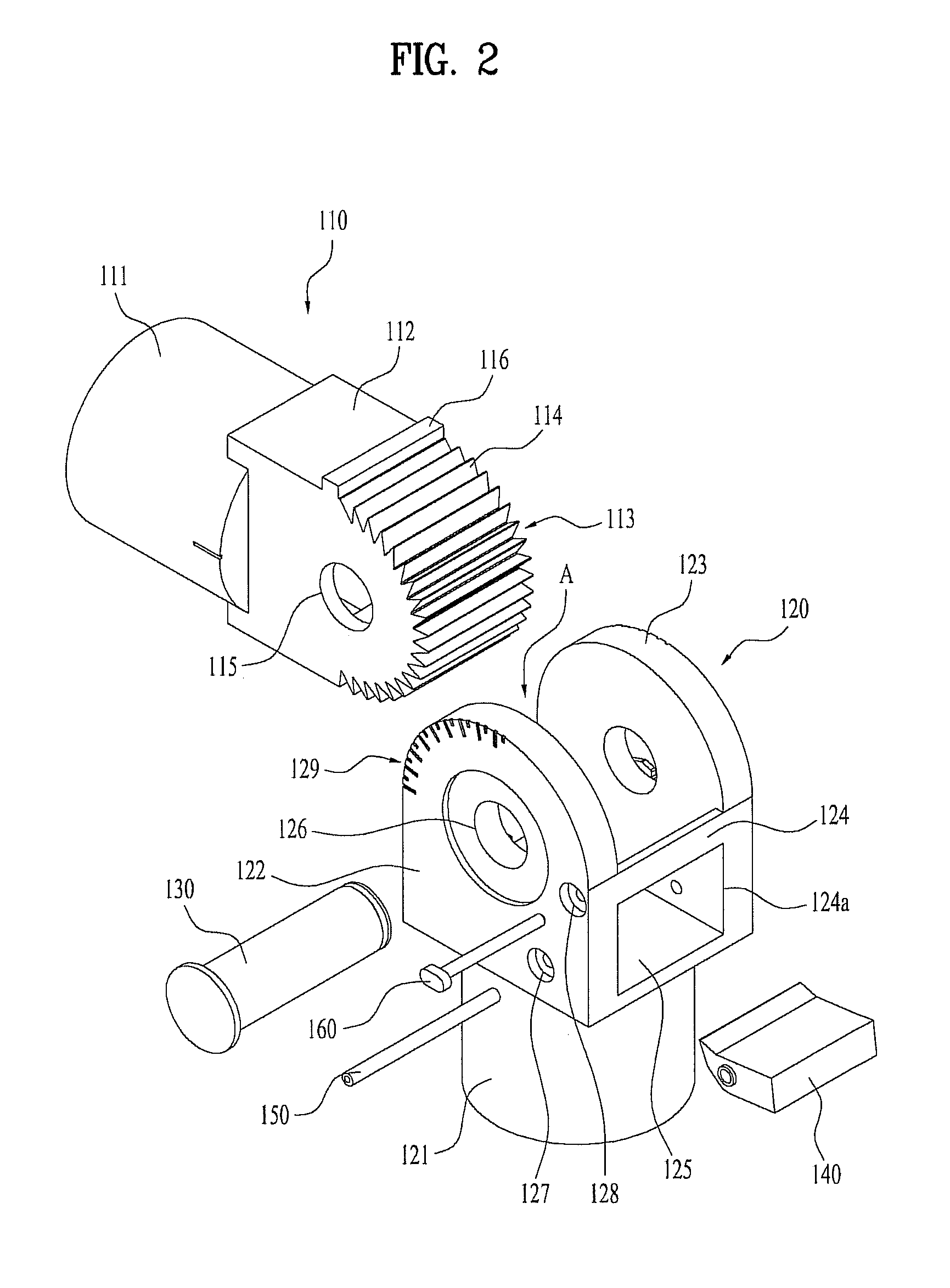
[0047]FIG. 2 is a cut-away perspective view of a lighting apparatus according to a first embodiment of the present invention. FIG. 3 is a perspective view of components shown in FIG. 2 that are assembled to each other. FIGS. 4 and 5 are conceptual diagrams to explain a tilted angle adjustment state of the lighting apparatus according to the first embodiment of the present invention.

[0048]Referring to FIGS. 2 to 5, the lighting apparatus 100 according to the first embodiment of the present invention includes a body 1 having a substrate, an LED mounted on the substrate, an electrical part unit to supply the electricity to the LED and a heat sink to radiate the heat generated from the LED, a connection member 110 having a side 111 provided in the body 1 and the other side 112 where a tooth part 113 is provided, a support member 120 to support the connection...

second embodiment

[0118]Referring to FIGS. 7 and 8, the lighting apparatus 200 may include a body (1, see FIG. 1), a connection member 210 provided in the body 1, a support member 220 where the connection member 210 is rotatably coupled, and a holding member 240 rotatably coupled to the support member 220 to maintain the connection member 210 in a rotation locking state to maintain the body 1 tilted at a predetermined angle.

[0119]As mentioned above, the body 1 composing the lighting apparatus 100 according to the first embodiment has the same structure as the lighting apparatus 200 according to the second embodiment does.

[0120]However, the connection member 210, the support member 220 and the holding member 240 which compose the lighting apparatus 200 according to the second embodiment are different from the connection member 110, the support member 120 and the holding member 140 which compose the lighting apparatus 100 according to the first embodiment. Such differences will be explained in detail ...


PUM


Abstract

There is disclosed a lighting apparatus, more particularly, a lighting apparatus that is able to control a radiation angle of a body provided therein, with being fitted to a lighting space and in an installation spot or in a state of being installed, and to enhance luminance efficiency and save the energy.

Description

CROSS REFERENCE TO RELATED APPLICATION[0001]This application claims the benefit of the Patent Korean Application No. 10-2012-0104930, filed on Sep. 21, 2012, which is hereby incorporated by reference as if fully set forth herein.BACKGROUND OF THE DISCLOSURE[0002]1. Field of the Disclosure[0003]The present invention relates to a lighting apparatus, more particularly, to a lighting apparatus that is able to control a radiation angle of a body provided therein to be fitted to a lighting space.[0004]2. Discussion of the Related Art[0005]Generally, a light source used for lighting in recent may include an incandescent lamp, an electric discharge lamp and a fluorescent lamp and such light sources are used for various purposes such as for domestic usage, landscape usage and industrial usage.[0006]The incandescent lamp which is a resistive light source out of such the light sources has disadvantages of deteriorating light emitting efficiency and heat radiation. The electric discharge lamp h...

Claims


Application Information

Patent Timeline
IPC IPC(8): F21V29/00
CPCF21V29/00F16M11/10F16M2200/024F21S8/033F21S8/086F21V21/30F21V29/74F21Y2105/10F21Y2115/10F21V17/02F21V21/14
Inventor AHN, TEAJEONG
Owner LG ELECTRONICS INC
Why Eureka
Try Eureka