Exhaust aftertreatment system and method

Inactive Publication Date: 2014-04-03
CATERPILLAR INC
View PDF18 Cites 23 Cited by
  • Summary
  • Abstract
  • Description
  • Claims
  • Application Information

AI Technical Summary

Benefits of technology

This patent is about a system and method for treating engine exhaust gas. The system includes an oxidation catalyst, a NOX adsorber, and a turbine, which work together to reduce NOx emissions. The system also includes a particulate filter coated with a selective catalytic reduction catalyst. The method involves converting NO in the exhaust gas to NO2 and adsorbing and storing NOx from the exhaust gas in an adsorbing location. The exhaust gas temperature is then increased and the CDS is activated. A reductant is then introduced into the exhaust gas to form NH3, which is converted into N2 and H2O downstream of the adsorbing location. This system and method can effectively reduce NOx emissions from engine exhaust gas.

Problems solved by technology

Complicated exhaust aftertreatment systems, developed in response to increased government regulation of engine emissions, can occupy large amounts of space in a vehicle or stationary application.
This can make designing machine systems and components to fit in the remaining space difficult.
Some engine and aftertreatment systems, engineered to meet new emission regulations, may have increased heat rejection.
With less space, cooling system designs can be challenging.
Since emission regulations must be met in a variety of conditions and temperatures, the aftertreatment components may be designed larger, and thus more expensive; or the engine may be run in a less fuel efficient manner; when exhaust gas temperatures are lower.
For example, when the engine is first started, especially at low ambient temperatures, the exhaust system temperatures may be too low for an SCR system to reach a light-off condition.
All these solutions involve additional cost.
Although the oxidation catalysts disclosed in Lambert are located upstream of the turbine, other aftertreatment devices may still occupy a large space, and may take some time to reach light-off temperature.

Method used


Image

  • Exhaust aftertreatment system and method
  • Exhaust aftertreatment system and method
  • Exhaust aftertreatment system and method

Examples


first embodiment

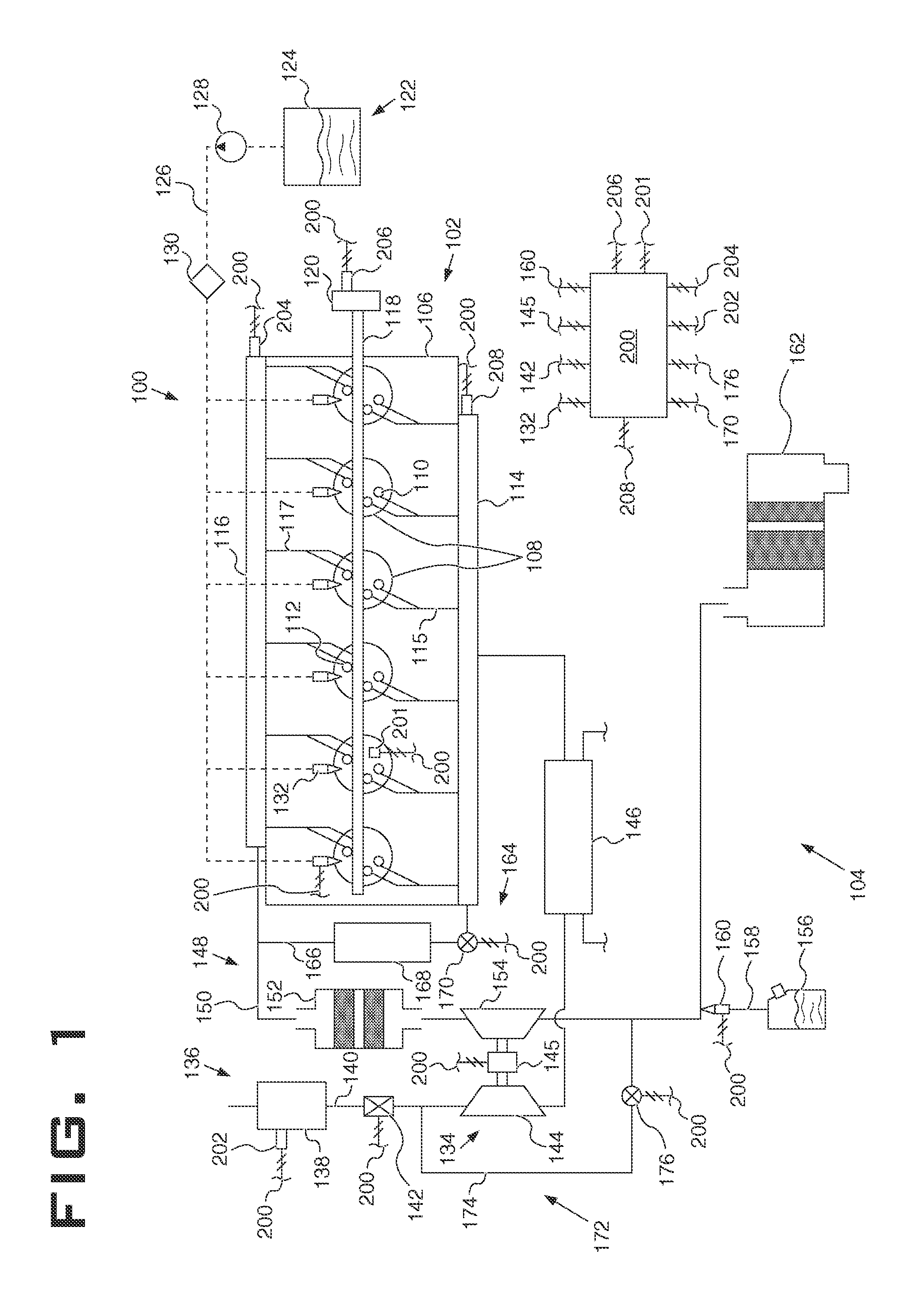
[0030]In the first embodiment, a high-pressure EGR system 164 operates to direct high-pressure exhaust gasses to the intake manifold 114. The high-pressure EGR system 164 includes a high-pressure EGR line 166 that communicates with the exhaust line 150 downstream of the exhaust manifold 116 and upstream of the pre-turbine module 152 and the turbine 154 to receive the high-pressure exhaust gasses being expelled from the combustion chambers 108. The system is thus referred to as a high-pressure EGR system 164 because the exhaust gasses received have yet to depressurize through the pre-turbine module 152 and the turbine 154. In an alternative embodiment the high-pressure EGR line 166 may communicate with the exhaust line 150 downstream of the pre-turbine module 152 and upstream of the turbine 154. The high-pressure EGR line 166 is also in fluid communication with the intake manifold 114. To control the amount or quantity of the exhaust gasses combined with the intake air, the high-pres...

second embodiment

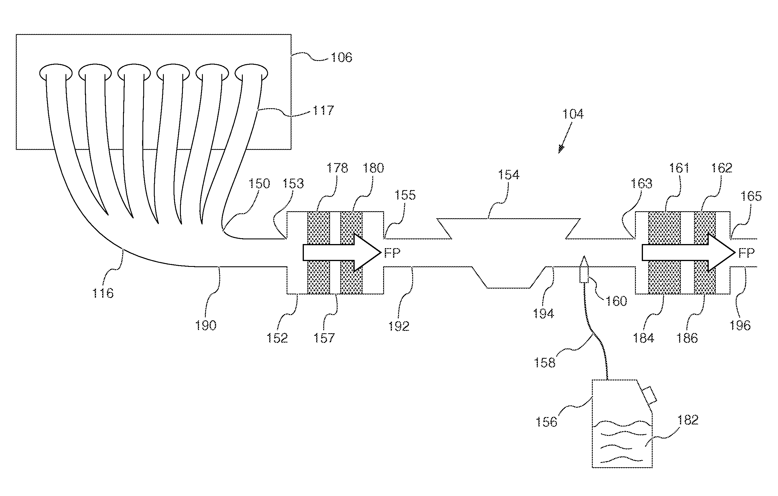
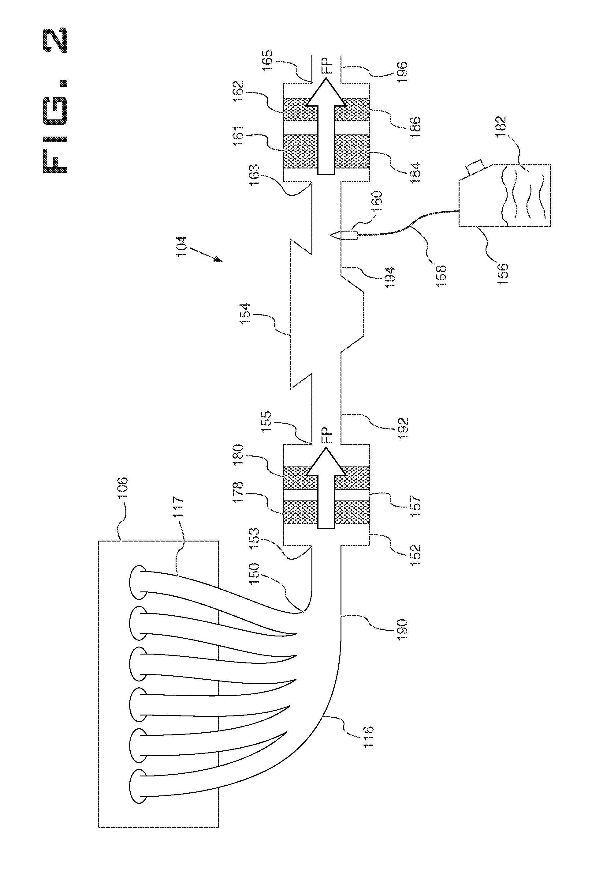
[0031]In the second embodiment, a low-pressure EGR system 172 directs low-pressure exhaust gasses to the intake line 140 before it reaches the intake manifold 114. The low-pressure EGR system 172 includes a low-pressure EGR line 174 that communicates with the exhaust line 150 downstream of the turbine 154 so that it receives low-pressure exhaust gasses that have depressurized through the pre-turbine module 152 and the turbine 154, and delivers the exhaust gasses upstream of the compressor 144 so the exhaust gasses can mix and be compressed with the incoming air. The system 172 is thus referred to as a low-pressure EGR system 172 because it operates using depressurized exhaust gasses. To control the quantity of exhaust gasses re-circulated, the low-pressure EGR line 174 can also include a low pressure EGR valve 176.

[0032]To coordinate and control the various systems and components associated with the engine system 100, the system 100 can include an electronic or computerized control ...


PUM

PropertyMeasurementUnit
Temperatureaaaaaaaaaa
Pressureaaaaaaaaaa
Flow rateaaaaaaaaaa

Abstract

An engine exhaust gas treatment system includes an oxidation catalyst, a NOX adsorber, and a turbine. The oxidation catalyst and the NOX adsorber are fluidly connected to an exhaust manifold of the engine. The turbine is fluidly connected to, and downstream of the oxidation catalyst and the NOx adsorber.

Description

TECHNICAL FIELD[0001]The present disclosure relates generally to exhaust gas aftertreatment systems. Specifically, an embodiment of the present invention relates to an aftertreatment system with an aftertreatment device upstream of a turbine.BACKGROUND[0002]Complicated exhaust aftertreatment systems, developed in response to increased government regulation of engine emissions, can occupy large amounts of space in a vehicle or stationary application. This can make designing machine systems and components to fit in the remaining space difficult. Some engine and aftertreatment systems, engineered to meet new emission regulations, may have increased heat rejection. With less space, cooling system designs can be challenging. Many aftertreatment devices are more efficient when exhaust gasses are at higher temperatures. Since emission regulations must be met in a variety of conditions and temperatures, the aftertreatment components may be designed larger, and thus more expensive; or the en...

Claims


Application Information

Patent Timeline
IPC IPC(8): B01D53/94F01N3/035F02M25/07F01N3/10F02B37/10
CPCF01N3/035B01D53/9418B01D53/9422B01D53/944B01D53/9477B01D2255/915F01N3/0814F01N3/106F01N3/2066F02B37/04F01N2340/06F01N2570/18F01N2610/02F01N13/009F02M26/00Y02T10/12
Inventor CHAVANNAVAR, PRAVEEN
Owner CATERPILLAR INC
Why Eureka
Try Eureka