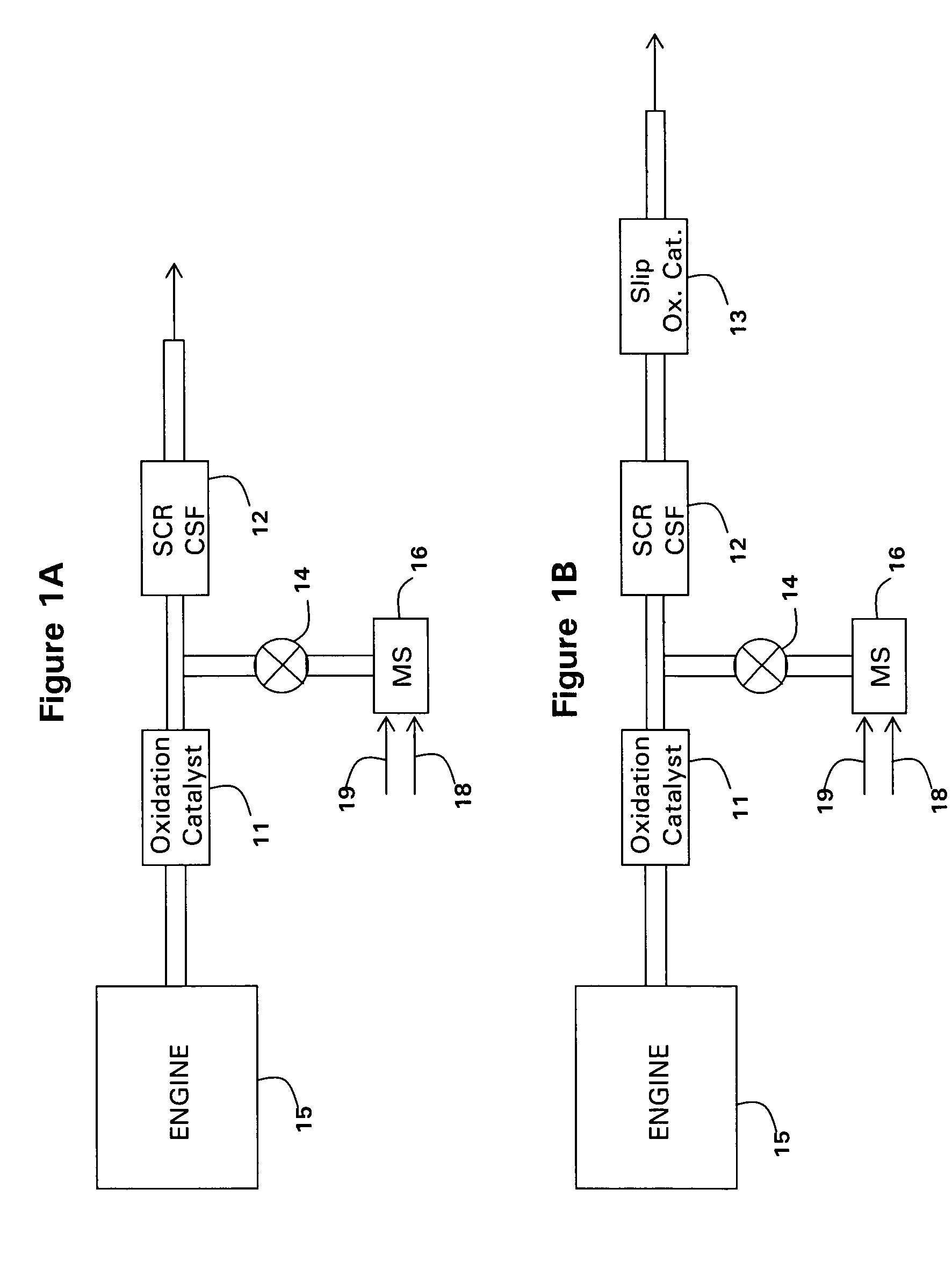
Catalyzed SCR filter and emission treatment system

a technology of emission treatment system and scr filter, which is applied in the direction of catalyst activation/preparation, machine/engine, surface covering, etc., can solve the problems of unacceptably high back pressure within the exhaust system, carbon soot particles that require temperatures in excess of 500° c. to burn, and the catalytic effect of commonly used scr catalyst compositions such as mixed oxides of vanadium and titanium is less

Active Publication Date: 2007-06-12
BASF CORP
View PDF42 Cites 296 Cited by
  • Summary
  • Abstract
  • Description
  • Claims
  • Application Information

AI Technical Summary

Benefits of technology

[0007]Provisions are generally introduced to lower the soot burning temperature in order to provide for passive regeneration of the filter. The presence of a catalyst promotes soot combustion, thereby regenerating the filters at temperatures accessible within the diesel engine's exhaust under realistic duty cycles. In this way a catalyzed soot filter (CSF) or catalyzed diesel particulate filter (CDPF) is effective in providing for >80% particulate matter reduction along with passive burning of the accumulating soot, and thereby promoting filter regeneration.
[0008]Future emissions standards adopted throughout the world will also address NOx reductions from diesel exhaust. A proven NOx abatement technology applied to stationary sources with lean exhaust conditions is Selective Catalytic Reduction (SCR). In this process, NOx is reduced with ammonia (NH3) to nitrogen (N2) over a catalyst typically composed of base metals. The technology is capable of NOx reduction greater than 90%, and thus it represents one of the best approaches for achieving aggressive NOx reduction goals. SCR is under development for mobile applications, with urea (typically present in an aqueous solution) as the source of ammonia. SCR provides efficient conversions of NOx as long as the exhaust temperature is within the active temperature range of the catalyst.
[0009]While separate substrates each containing catalysts to address discrete components of the exhaust can be provided in an exhaust system, use of fewer substrates is desirable to reduce the overall size of the system, to ease the assembly of the system, and to reduce the overall cost of the system. One approach to achieve this goal is to coat the soot filter with a catalyst composition effective for the conversion of NOx to innocuous components. With this approach, the catalyzed soot filter assumes two catalyst functions: removal of the particulate component of the exhaust stream and conversion of the NOx component of the exhaust stream to N2.
[0010]Coated soot filters that can achieve NOx reduction goals require a sufficient loading of SCR catalyst composition on the soot filter. The gradual loss of the catalytic effectiveness of the compositions that occurs over time through exposure to certain deleterious components of the exhaust stream augments the need for higher catalyst loadings of the SCR catalyst composition. However, preparation of coated soot filters with higher catalyst loadings can lead to unacceptably high back pressure within the exhaust system. Coating techniques that allow higher catalyst loadings on the wall flow filter, yet still allow the filter to maintain flow characteristics that achieve acceptable back pressures are therefore desirable.

Problems solved by technology

Unfortunately, the carbon soot particles require temperatures in excess of 500° C. to burn under oxygen rich (lean) exhaust conditions.
However, preparation of coated soot filters with higher catalyst loadings can lead to unacceptably high back pressure within the exhaust system.
For example, combustion of the soot fraction of the particulate matter often leads to temperatures above 700° C. Such temperatures render many commonly used SCR catalyst compositions such as mixed oxides of vanadium and titanium less catalytically effective.

Method used


Image

  • Catalyzed SCR filter and emission treatment system
  • Catalyzed SCR filter and emission treatment system
  • Catalyzed SCR filter and emission treatment system

Examples


example 1

Coating of Ceramic Wall Flow Filters

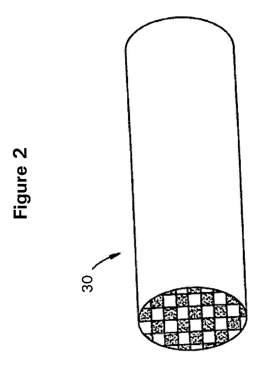
[0074]Cordierite ceramic wall flow filter substrates (product name C611, NGK Insulators, Ltd.) having dimensions of 5.66×6 inches, a wall thickness of 0.012 in, an average pore size of 25 microns and 60% wall porosity were used to prepare catalyst-coated soot filters.

[0075]A catalyst slurry containing 27% by weight solids content was formed from copper-exchanged beta zeolite (containing 2 wt. % of copper), additional CuSO4 (sufficient to provide 9.5 wt. % of copper), and 7 wt. % ZrO2 and de-ionized water (wt. % based on the weight of the beta zeolite). The copper-exchanged beta zeolite was prepared as in U.S. Pat. No. 5,516,497.

[0076]An identical procedure was used to prepare two of the filter substrates according to a preferred embodiment of the invention. The wall flow substrate was:

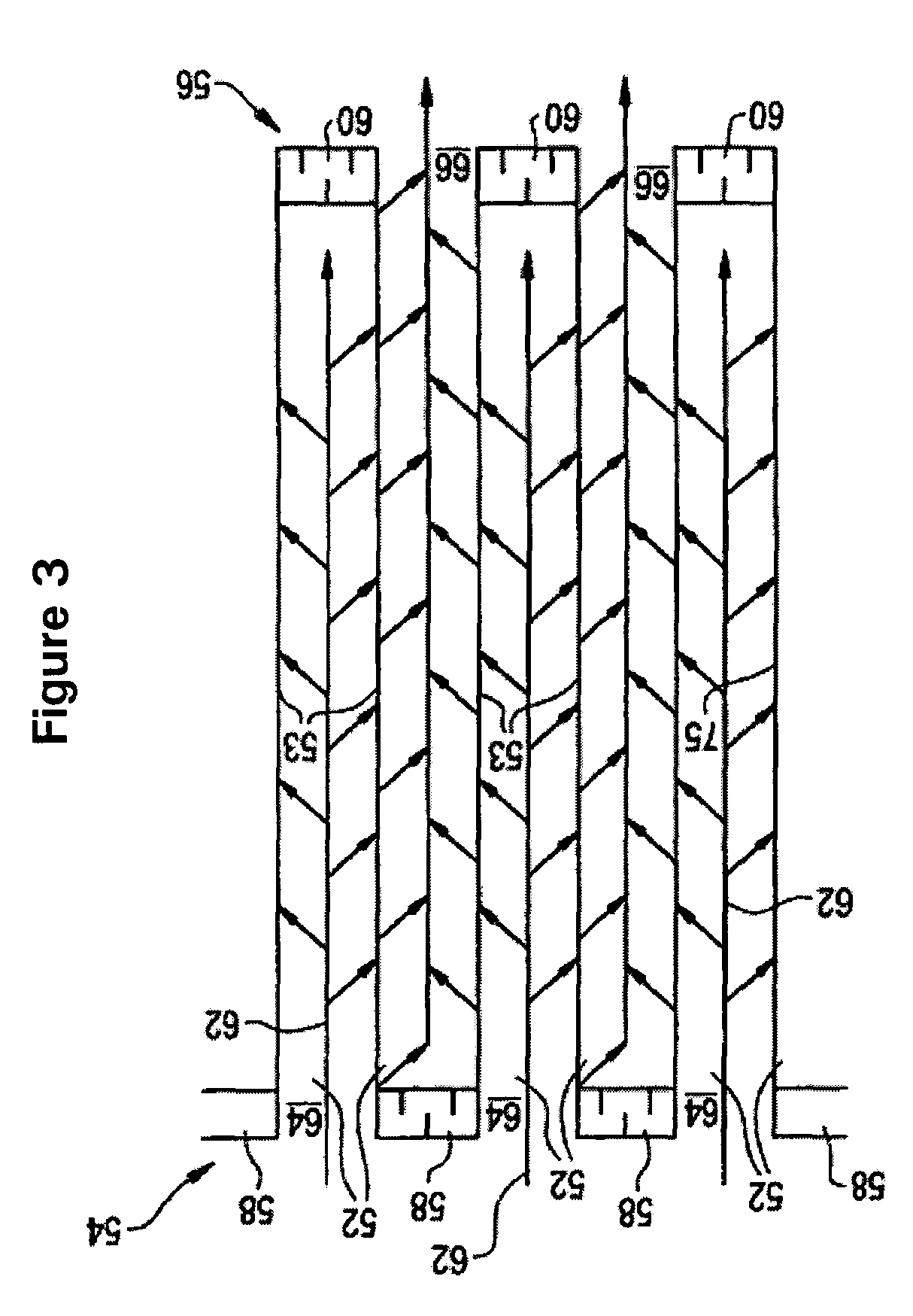
[0077](1) dipped into the slurry to a depth sufficient to coat the channels of the substrate along the entire axial length of the substrate from one direction;

[0078]...

example 2

Evaluation of Back Pressures for Coated Soot Filters

[0085]The pressure drop across the uncoated and coated filters was evaluated using the commercially available automated equipment, Super Flow SF 1020, (Probench). This equipment is designed specifically for measuring pressure drops as a function of air flow. Data from this equipment provides a plot of the pressure drop at ambient conditions as a function of the air flow. The pressure drop is a measure of how easily air flows through the filter. In diesel engine applications, lower pressure drops are desirable since the engine must expend power to move the air. Therefore, the larger the pressure drop, the greater the amount of engine power that is lost to pumping air. This lost power reduces the engine power that is available to the wheels.

[0086]FIG. 5 summarizes the pressure drop across the coated filters, Catalyst A1, A2 and B1, as well as an uncoated filter of the identical dimensions. The filters coated according to Steps (1) th...

example 3

Demonstration of Particulate Removal by the SCR Catalyst

[0087]When applied to the wall flow filter, the catalyst composition should ideally aid in the regeneration of the filter. Therefore, the SCR catalyst composition disposed on the filter is preferably able to catalyze the oxidation of soot and VOF portions of the particulate. To be effective in reducing NOx and particulate mass the SCR catalyst should preferably not oxidize ammonia or SO2 to make SO3. One way of evaluating a catalyst's ability to oxidize carbon and VOF is by the use of combined Thermal Gravimetric Analysis (TGA) and Differential Thermal Analysis (DTA). The TGA measures the weight loss of a sample while the DTA measures the change in sample's heat capacity versus a reference. In this experiment, a dried and calcined portion of the catalyst slurry was mixed with 6% by weightfube oil, to simulate the VOF portion of the lube, and 14% by weight carbon black, to simulate the soot fraction of the particulate. The mixtu...


PUM

PropertyMeasurementUnit
concentrationaaaaaaaaaa
pore sizeaaaaaaaaaa
porosityaaaaaaaaaa

Abstract

Provided is an emission treatment system and method for simultaneously remediating the nitrogen oxides (NOx), particulate matter, and gaseous hydrocarbons present in diesel engine exhaust streams. The emission treatment system has an oxidation catalyst upstream of a soot filter coated with a material effective in the Selective Catalytic Reduction (SCR) of NOx by a reductant, e.g., ammonia. Also provided is a method for disposing an SCR catalyst composition on a wall flow monolith that provides adequate catalyst loading, but does not result in unsuitable back pressures in the exhaust.

Description

[0001]The present invention relates to an emission treatment system having an oxidation catalyst upstream of a soot filter coated with a material effective in the Selective Catalytic Reduction (SCR) of NOx by a reductant, e.g., ammonia. In one embodiment, the system provides an effective method of simultaneously remediating the nitrogen oxides (NOx), particulate matter, and gaseous hydrocarbons present in diesel engine exhaust streams.[0002]Diesel engine exhaust is a heterogeneous mixture which contains not only gaseous emissions such as carbon monoxide (“CO”), unburned hydrocarbons (“HC”) and nitrogen oxides (“NOx”), but also condensed phase materials (liquids and solids) which constitute the so-called particulates or particulate matter. Often, catalyst compositions and substrates on which the compositions are disposed are provided in diesel engine exhaust systems to convert certain or all of these exhaust components to innocuous components. For example, diesel exhaust systems can ...

Claims


Application Information

Patent Timeline
Patent Type & Authority Patents(United States)
IPC IPC(8): B01D50/00B01D53/94F01N3/023F01N3/20F01N13/02
CPCB01D5/0054B01D19/0005B01D19/0036B01D53/9418B01D53/945B01J29/7615B01J37/0246F01N3/0231F01N3/106F01N3/2066F01N13/009F01N3/2828F01N3/2892B01J29/76F01N3/10B01D5/009Y10T29/49345B01D53/9477B01D2251/2062B01D2251/2067B01D2255/102B01D2255/20715B01D2255/20738B01D2255/20761B01D2255/502B01D2255/9155B01D2255/9202B01D2255/9205B01D2258/012F01N2370/04F01N2510/063F01N2610/02F01N2610/08Y10S55/30Y10S55/10Y02T10/22Y02T10/24F01N2330/06F01N2330/30B01D53/944Y02T10/12B01D53/94B01J35/04B01D53/9413B01D2257/404B01J35/1076B01D2255/50B01J37/0236B01J37/024B01J37/08
Inventor PATCHETT, JOSEPH ALLANDETTLING, JOSEPH CHARLESPRZYBYLSKI, ELIZABETH ALINA
Owner BASF CORP
Why Eureka
Try Eureka