Gear and manufacturing method for the same

Active Publication Date: 2014-04-03
ENPLAS CORP
View PDF17 Cites 11 Cited by
  • Summary
  • Abstract
  • Description
  • Claims
  • Application Information

AI Technical Summary

Benefits of technology

[0017]According to the manufacturing method of the gear of the second aspect, the form of the tooth root side of each of the plurality of teeth can be identical to the form shaped by the gear-generation with the rack-type cutter having the blade edge including the round portion with the curve defined by the quadratic function, without forming the triangu

Problems solved by technology

In such a gear, a stress might tend to be concentrated to the recess hole of the tooth bottom during the engagement with

Method used


Image

  • Gear and manufacturing method for the same
  • Gear and manufacturing method for the same
  • Gear and manufacturing method for the same

Examples


first embodiment

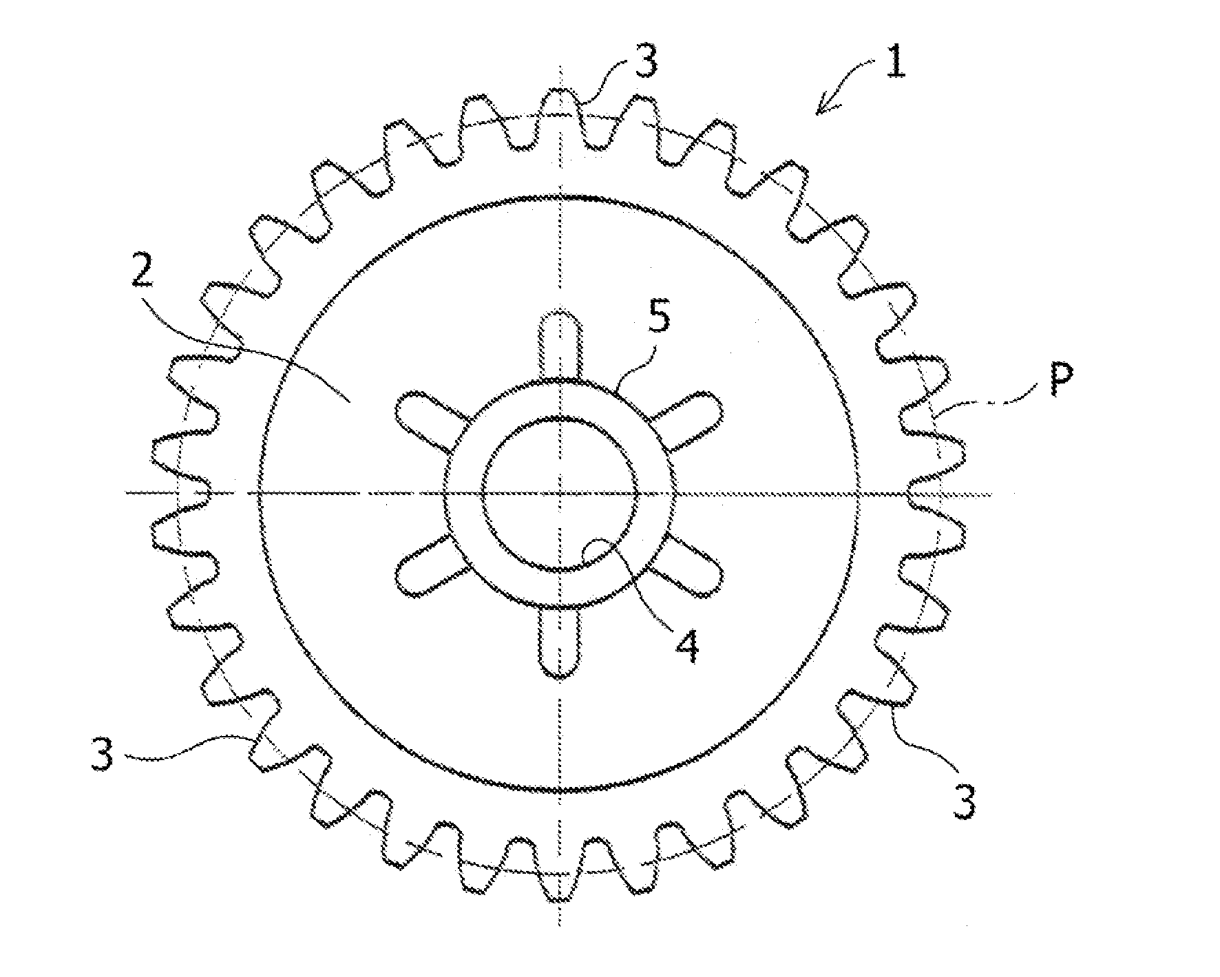
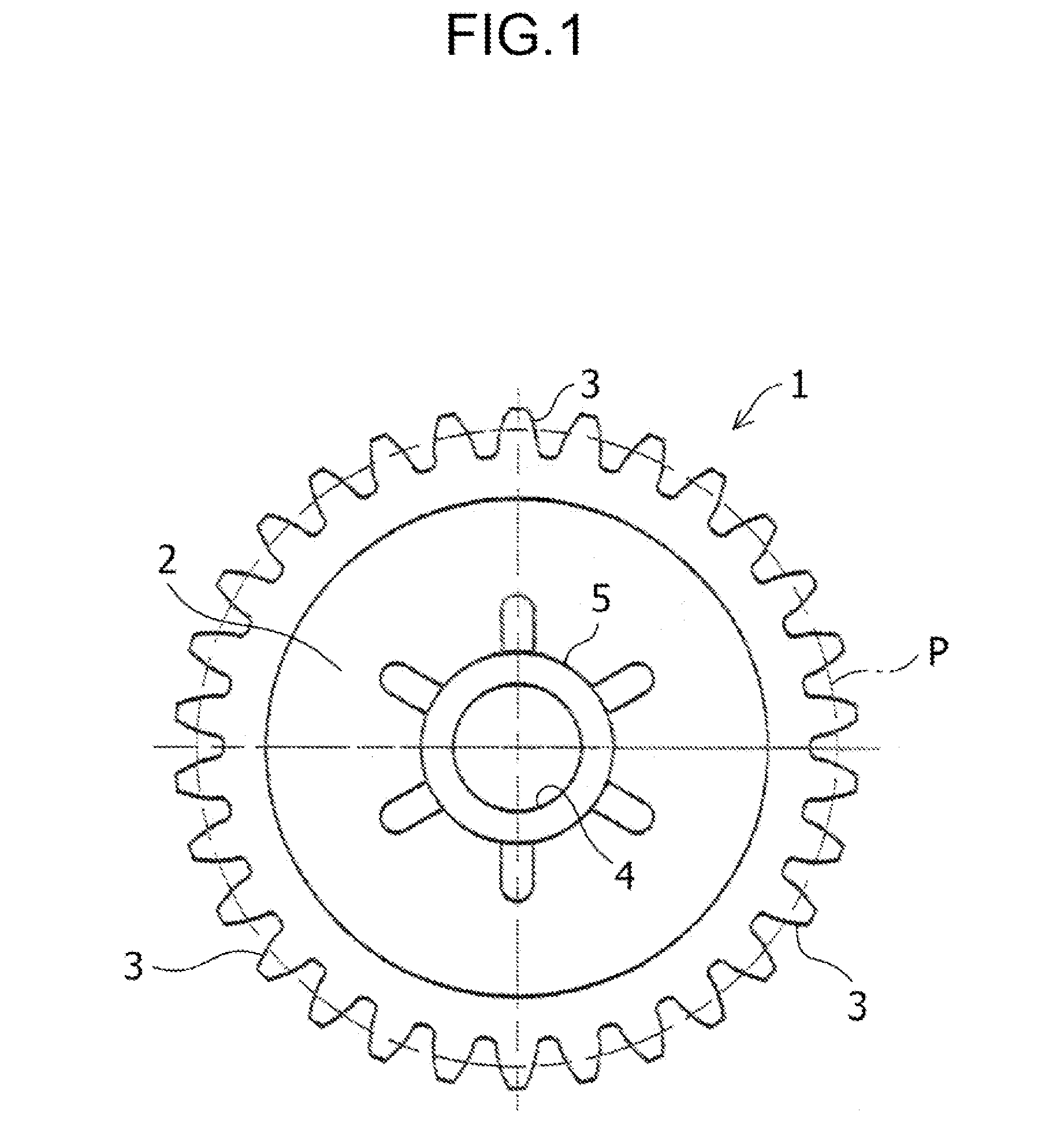
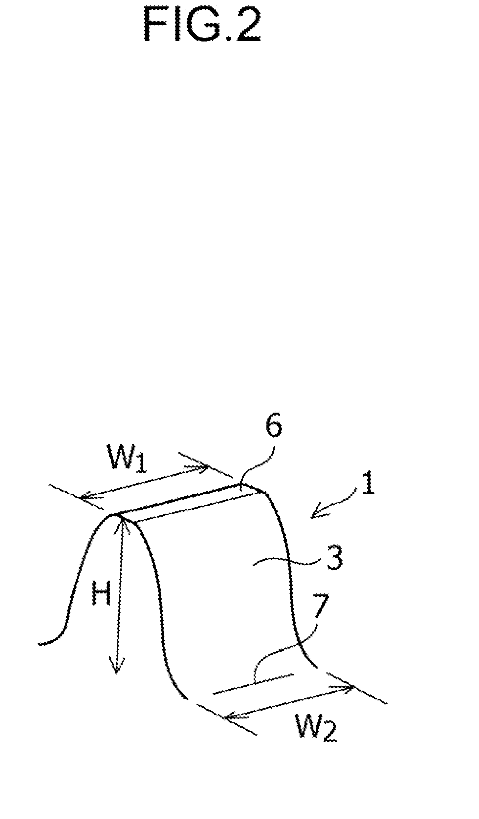
[0038]Such a tooth profile may be set as follows. First, in FIG. 4, when viewed in a cross section of the tooth 3 perpendicular to the tooth surface width direction of the tooth 3 (referred to as “a tooth perpendicular section”), the profile of the second curved surface d is set to be a curve with a curvature radius which does not interfere with a locus of motion of the engaged teeth of the corresponding gear, and a curve which is in contact with the tooth bottom surface 7 of the above-mentioned standard gear (see, FIG. 2). That is, the locus of motion of a tooth surface on a tooth top side of the corresponding gear (not shown) which is brought into contact with the teeth 3 of the gear at the time of engagement can be a trochoid curve T as illustrated in FIG. 4. This trochoid curve T remains within a region which does not reach the tooth bottom surface 7 in the tooth space between the teeth 3, 3 of the standard gear. In this state, the profile may be set to be a curve with the curva...

second embodiment

[0049]In FIG. 10, a detailed profile of the B-portion of FIG. 9 is illustrated. Referring to FIG. 10, in general, the blade 11 of the rack-type cutter 10 has a portion of the blade edge 12 formed as an arc when a gear having a high tooth-root strength is manufactured by the gear-generation in a general gear design. That is, a portion defined by points C1, D, C2 of the blade edge 12 is formed as an arc g having a predetermined radius (conventional example). On the other hand, the blade 11 of the rack-type cutter 10 used to manufacture the gear 1 has a portion defined by points C1, D, C2 of the blade edge 12 as illustrated in FIG. 10 replaced with a round portion represented by a curve h defined by the quadratic function. In this case, the curve h defined by the quadratic function is located inside the arc g of the conventional example, and accordingly, the blade edge 12 becomes slightly narrow. The gear 1 which is subjected to the gear-generation with the rack-type cutter 10 having ...


PUM

PropertyMeasurementUnit
Radiusaaaaaaaaaa

Abstract

A gear includes teeth 3 to be engaged with teeth of a corresponding gear to transmit a rotational motion, in which a form (b) of a tooth root side of each tooth 3 includes: a first curved surface c which smoothly connects with a tooth surface a having an involute curve and has a profile represented by a curve which is convex in a direction opposite to the involute curve of the tooth surface a; and a second curved surface d which smoothly connects with the first curved surface c and has a profile defined by a quadratic function having a curve being convex in the same direction as that of the first curved surface c. Therefore, a stress generated on the tooth root side at the time of engagement with the teeth of the corresponding gear can be reduced, and the strength of the teeth can be increased.

Description

BACKGROUND OF THE INVENTION[0001]1. Field of the Invention[0002]The present invention relates to a gear including a plurality of teeth to be engaged with teeth of a corresponding gear to thereby transmit a rotational motion between two shafts, and in particular, relates to a gear having a tooth profile that can reduce a stress generated on a tooth root side at the time of engagement with teeth of a corresponding gear and can increase a strength of teeth of the gear, and relates to a manufacturing method therefor.[0003]2. Description of Related Art[0004]Conventionally, numerous attempts have been made to increase a strength of teeth of a gear used in a power transmission mechanism, such as in an automobile, a precision machine, and the like.[0005]This kind of gear includes a ring gear with teeth and tooth spaces, in which the teeth can be brought into engagement with a corresponding gear (pinion) via tooth flanks, in which the tooth flanks, after a final engagement point of the pinio...

Claims


Application Information

Patent Timeline
IPC IPC(8): B23F17/00F16H55/08
CPCF16H55/0806B23F17/005Y10T74/1987Y10T409/101431
Inventor OHMI, KENJI
Owner ENPLAS CORP
Why Eureka
Try Eureka