Concentrated solar cell and manufacturing method for the same

a solar cell and concentrated technology, applied in the direction of photovoltaics, electrical appliances, semiconductor devices, etc., can solve the problems of ineffective use of solar cell elements and ineffective use of sunlight, and achieve the effect of efficient concentrating sunlight and improving the output characteristic of solar cells

Inactive Publication Date: 2014-04-03
SHARP KK
View PDF4 Cites 11 Cited by
  • Summary
  • Abstract
  • Description
  • Claims
  • Application Information

AI Technical Summary

Benefits of technology

[0049]According to a concentrated solar cell of the present invention, the optical member is given an integrated structure in which the intermediate air layer is eliminated, thus enabling efficiently concentrating sunlight concentrated by an optical refraction portion without the concentrated sunlight undergoing intensity reflection, and this makes it possible to improve the output characteristic of the solar cell.

Problems solved by technology

Also, in recent years, technology has been proposed for reducing the usage of solar cell elements, which are expensive among the members (parts) configuring a solar power generation device.
However, if the position of a solar cell element is fixed, the sunlight is almost incident at an oblique angle, and sunlight cannot be used effectively.

Method used


Image

  • Concentrated solar cell and manufacturing method for the same
  • Concentrated solar cell and manufacturing method for the same
  • Concentrated solar cell and manufacturing method for the same

Examples


embodiment 1

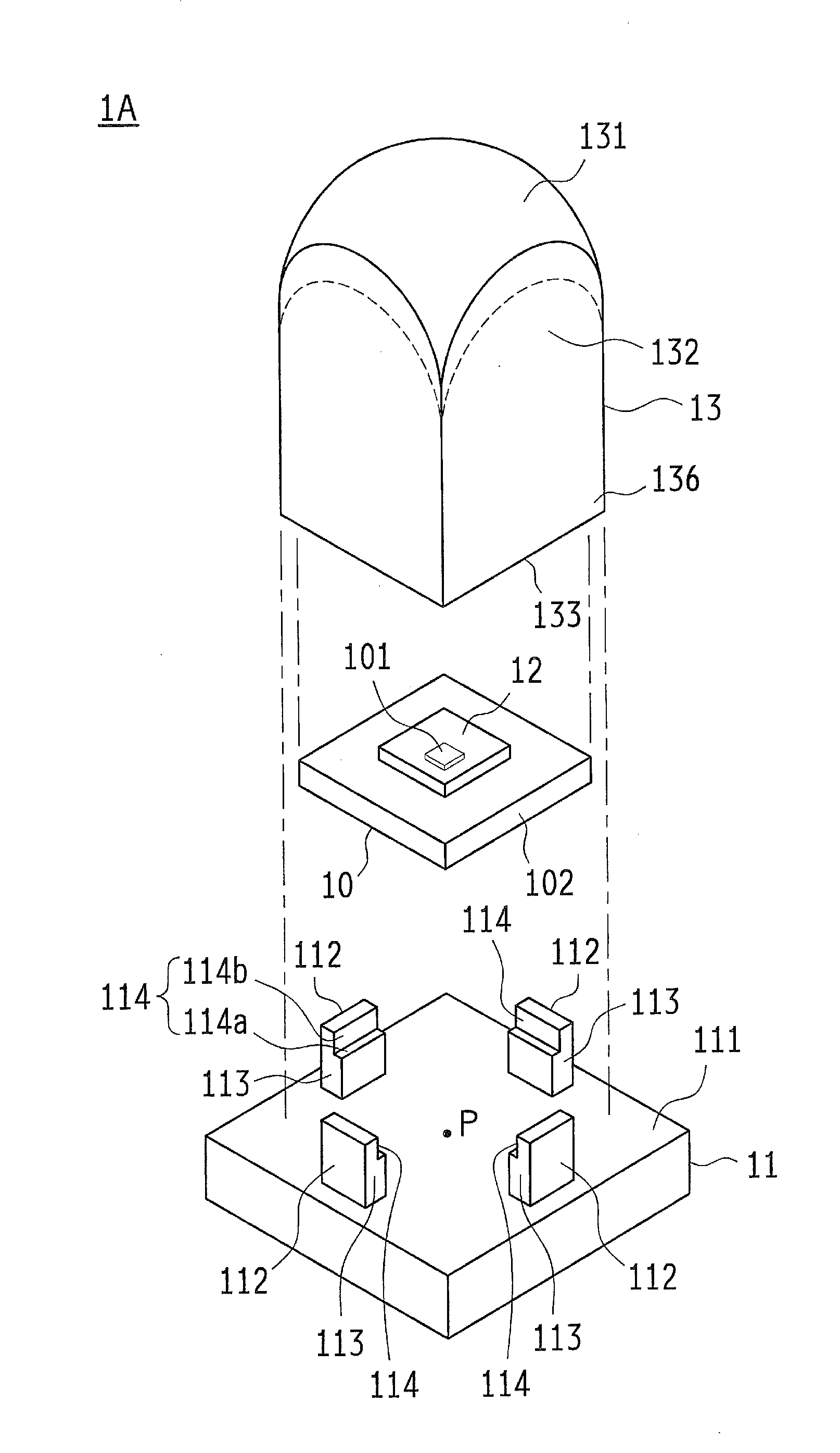
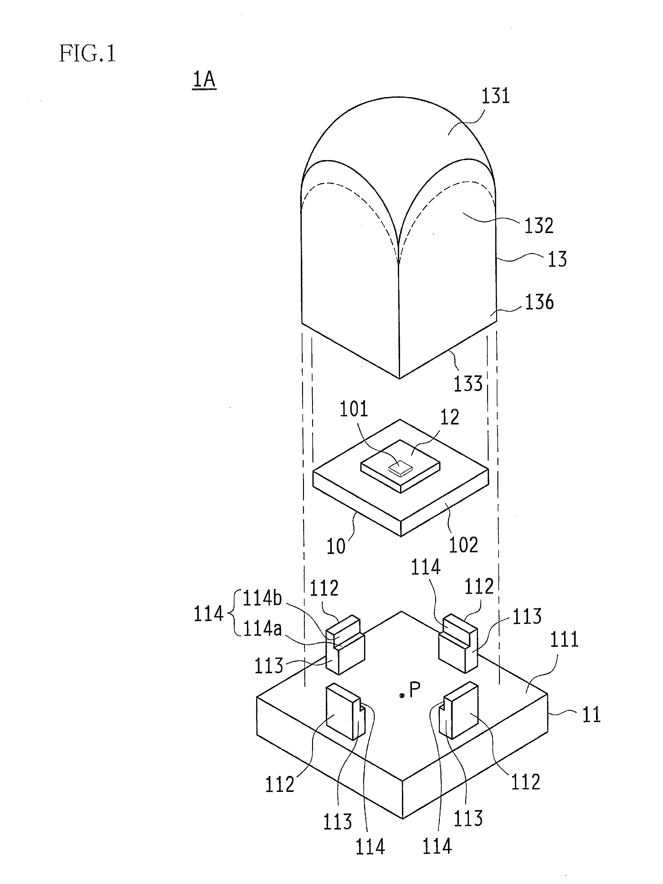
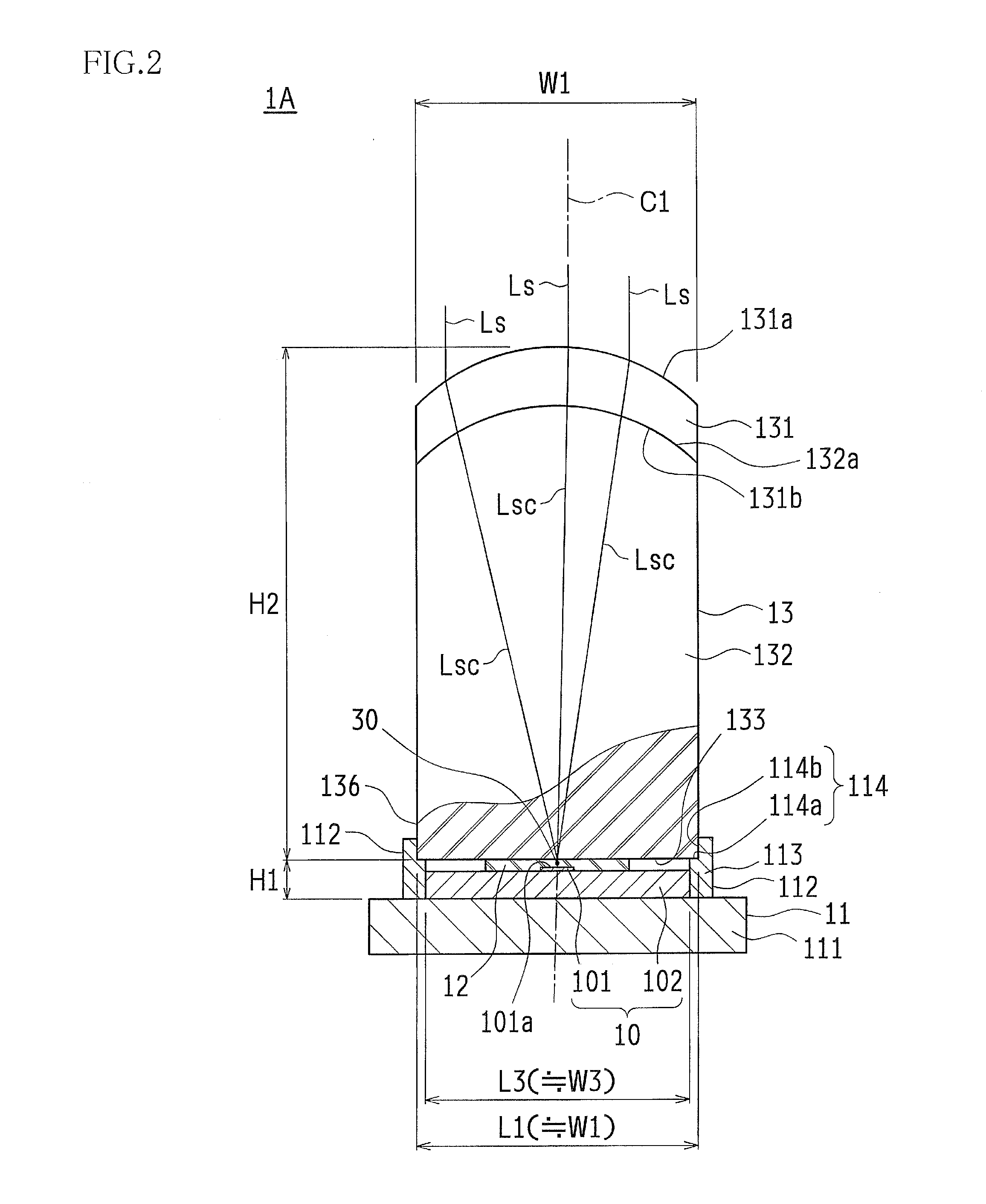
[0068]FIG. 1 is an exploded perspective view of constituent members of a concentrated solar cell according to Embodiment 1, and FIG. 2 is a side view showing a partially fractured view of the concentrated solar cell according to Embodiment 1.

[0069]A concentrated solar cell 1A according to Embodiment 1 is configured so as to include a solar cell substrate 10, which is obtained by mounting a solar cell element 101 on a receiver substrate (element substrate) 102, a sealing portion 12 provided on the receiver substrate 102 so as to cover the solar cell element 101, an integrated-structure optical member 13 that is provided on the sealing portion 12 and concentrates sunlight on the solar cell element 101, and a support member 11 that integrally supports the receiver substrate 102 and the optical member 13.

[0070]The solar cell element 101 is constituted by an inorganic material such as Si, GaAs, CuInGaSe, or CdTe. Also, various modes of structures can be applied to the solar cell element ...

embodiment 2

[0103]FIGS. 6 and 7 are side views showing a partially fractured view of a concentrated solar cell 1B according to Embodiment 2. FIG. 8A is a perspective view of the optical member 13 according to Embodiment 2 as viewed from above, and FIG. 8B is a perspective view of the same as viewed from the bottom face side.

[0104]In the concentrated solar cell 1B of Embodiment 2, a columnar optical portion 134 is integrally formed on the concentrated light emission portion 133 of the optical member 13 in the concentrated solar cell 1A of Embodiment 1. The columnar optical portion 134 is integrally formed on a portion of the concentrated light exit portion 133 where the concentrated light focal point group 30 is located, that is to say, a location in the central portion (centerline C1 of the optical base portion 132) of the concentrated light exit portion 133.

[0105]This configuration enables the optical member 13 to have the effects of the optical member 13 described in Embodiment 1 as well adva...

embodiment 3

[0129]FIG. 10 is a side view showing a partially fractured view of a concentrated solar cell 1C according to Embodiment 3. FIG. 11 is a perspective view of the arrangement of solar cell elements 101 on a receiver substrate (element substrate) 102 in the concentrated solar cell 1C according to Embodiment 3. FIG. 12A is a perspective view of an optical member 14 according to Embodiment 3 as viewed obliquely from above. FIG. 12B is a perspective view of the optical member 14 according to Embodiment 3 as viewed from the bottom face side.

[0130]The concentrated solar cell 1C according to Embodiment 3 is configured such that multiple solar cell elements 101 are mounted on the receiver substrate 102, and the optical member 14 serving as the optical member of the concentrated solar cell 1C has multiple optical portions 15, each having a configuration similar to that of the optical member 13 of Embodiment 2 described above, in correspondence with the solar cell elements 101. For this reason, ...


PUM


Abstract

A concentrated solar cell has a sealing portion (12) provided on a receiver substrate (102) so as to cover a solar cell element (101) provided on the receiver substrate (102), and an optical member (13) that is provided on the sealing portion (12) and concentrates sunlight on the solar cell element (101). The optical member (13) is configured so as to include an optical refraction portion (131) having a curved face for refracting and concentrating sunlight, a concentrated light emission portion (133) that is arranged in close contact with the sealing portion (12) such that the sunlight concentrated by the optical refraction portion (131) is emitted toward the solar cell element (101), and an optical base portion (132) arranged between the optical refraction portion (131) and the concentrated light emission portion (133). Also, the optical member (13) has an integrated structure in which there is no intermediate air layer from the optical refraction portion (131) to the concentrated light emission portion (133) with the optical base portion (132) therebetween.

Description

TECHNICAL FIELD[0001]The present invention relates to a concentrated solar cell that includes an integrated-structure optical member that improves sunlight concentration efficiency and suppresses a reduction in output caused by sun tracking error, and a manufacturing method for the same.BACKGROUND ART[0002]Conventional solar power generation devices have generally had a non-concentrating fixed flat-plate structure in which solar cell elements are laid out without gaps to configure a solar power generation module for installation on a roof or the like.[0003]Also, in recent years, technology has been proposed for reducing the usage of solar cell elements, which are expensive among the members (parts) configuring a solar power generation device.[0004]Specifically, there has been a proposal for concentrating sunlight using optical lenses, reflecting mirrors, and the like, and irradiating a small-area solar cell element with the concentrated light in order to increase the amount of power...

Claims


Application Information

Patent Timeline
Patent Type & Authority Applications(United States)
IPC IPC(8): H01L31/052
CPCH01L31/0524H01L31/048H01L31/0543Y02E10/52
Inventor OKAMOTO, CHIKAOUEDA, KOHSUKE
Owner SHARP KK
Why Eureka
Try Eureka