Disc brake

a disc brake and disc technology, applied in the direction of fluid actuated brakes, gearing, mechanical equipment, etc., can solve the problems of difficult to secure the the meshing portion wears out, and the portion for transmitting durability decreases, so as to achieve the effect of reliability of the disc brak

Inactive Publication Date: 2014-04-03
HITACHI AUTOMOTIVE SYST LTD
View PDF1 Cites 32 Cited by
  • Summary
  • Abstract
  • Description
  • Claims
  • Application Information

AI Technical Summary

Benefits of technology

[0006]In view of the above, the present invention has an object to secure the reliability of a disc brake.
[0010]With the disc brake according to one embodiment of the present invention, the reliability of the disc brake may be secured.

Problems solved by technology

However, as in the disc brake of the invention disclosed in Japanese Patent Application Laid-open No. 2011-179569, when the portion for transmitting the rotation moves in the axial direction, wear of a meshing portion thereof is progressed.
This causes a fear of decrease in durability of the portion for transmitting the rotation, resulting in a problem in that the reliability of the disc brake is difficult to secure.

Method used


Image

  • Disc brake
  • Disc brake
  • Disc brake

Examples


Embodiment Construction

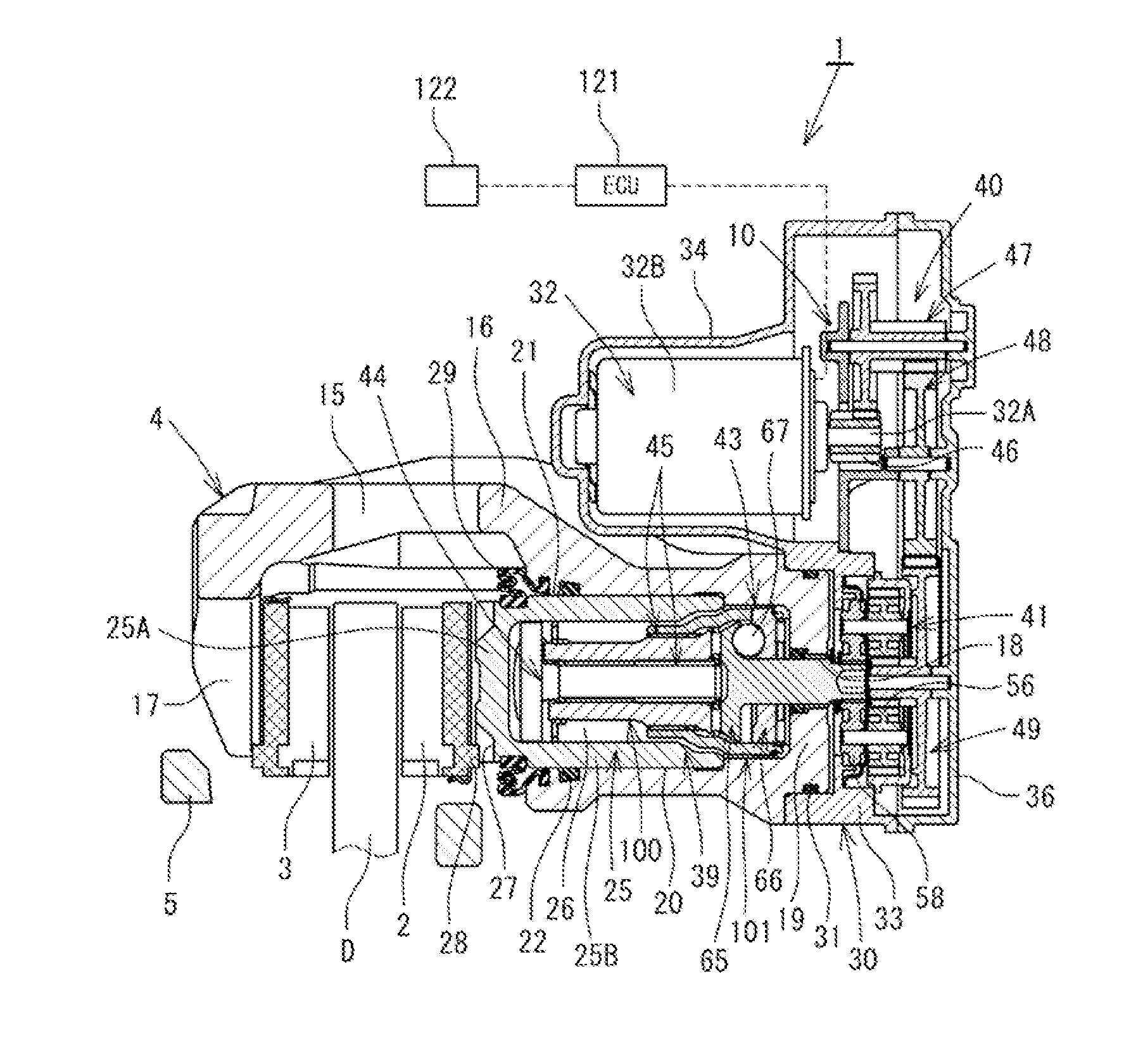
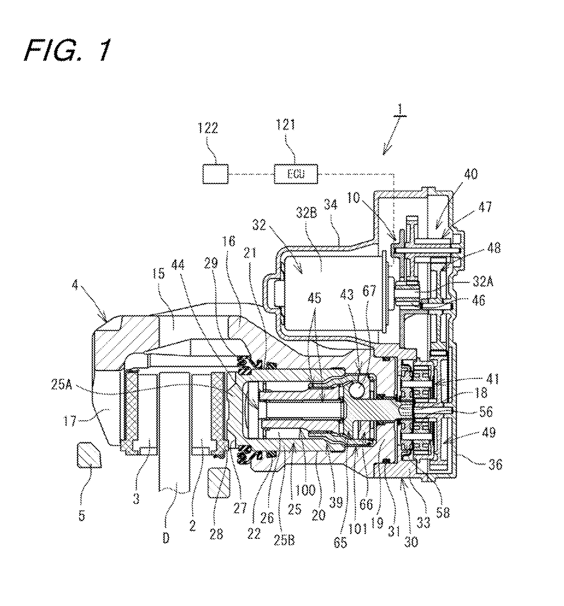
[0018]Now, an embodiment of the present invention is described in detail with reference to FIGS. 1 to 6. As illustrated in FIG. 1, a disc brake 1 according to this embodiment includes a pair of an inner brake pad 2 and an outer brake pad 3 arranged on both sides in an axial direction across a disc rotor D mounted on a rotary unit of a vehicle, and also includes a caliper 4. The disc brake 1 of this embodiment is a floating caliper disc brake. Note that, the pair of the inner brake pad 2 and the outer brake pad 3, and the caliper 4 are supported by a bracket 5, which is fixed to a stationary unit (not shown) such as a knuckle of the vehicle, so as to be movable in the axial direction of the disc rotor D.

[0019]A caliper body 15 as a main component of the caliper 4 includes a cylinder portion 16 arranged on a proximal end side to be opposed to the inner brake pad 2 on an inner side of the vehicle, and a claw portion 17 arranged on a distal end side to be opposed to the outer brake pad ...


PUM


Abstract

Provided is a disc brake with high reliability. In a disc brake (1), pins (60) press-fitted to a carrier (58) are inserted through hole portions (56B) of respective planet gears (56) in a freely rotatable and axially movable manner. Further, axial movement of the carrier (58) is allowed by an amount corresponding to a length of a clearance (37). As a result, when a rotary-to-linear ramp (65) advances during actuation of a parking brake, the carrier (58) and the pins (60) advance together with the rotary-to-linear ramp (65). Thus, actuation efficiency becomes excellent and durability is enhanced.

Description

BACKGROUND OF THE INVENTION[0001]1. Technical Field[0002]The present invention relates to a disc brake to be used for applying a brake to a vehicle.[0003]2. Background Art[0004]For example, Japanese Patent Application Laid-open No. 2011-179569 discloses a disc brake configured to move a piston through a drive force of an electric motor. In this disc brake, a rotational drive generated by the electric motor is transmitted through an intermediation of a pinion of a first speed reduction gear to a second speed reduction gear. In this case, the second speed reduction gear and a drive shaft integrally provided to a rotary-to-linear plate are coupled to each other so as to be relatively immovable in rotational and axial directions thereof. When the rotary-to-linear plate moves linearly, the second speed reduction gear moves in the axial direction together with the rotary-to-linear plate.[0005]However, as in the disc brake of the invention disclosed in Japanese Patent Application Laid-open...

Claims


Application Information

Patent Timeline
Patent Type & Authority Applications(United States)
IPC IPC(8): F16D55/226
CPCF16D55/226F16D65/18F16D65/567F16D2121/04F16D2121/24F16D2123/00F16D2125/36F16D2125/48F16D2125/50F16D65/095F16H1/28H02K7/116
Inventor SAKASHITA, TAKAYASUWATANABE, JUNTSURUMI, SATORUFUSE, TAKAAKI
Owner HITACHI AUTOMOTIVE SYST LTD
Why Eureka
Try Eureka