
High accuracy 1588 timestamping over high speed multi lane distribution physical code sublayers

a multi-lane distribution and physical code technology, applied in the field of clock synchronization in a packet-switched communication network, can solve problems such as path delay variability

Active Publication Date: 2014-04-03
MICROSEMI STORAGE SOLUTIONS
View PDF6 Cites 69 Cited by
  • Summary
  • Abstract
  • Description
  • Claims
  • Application Information

AI Technical Summary

Benefits of technology

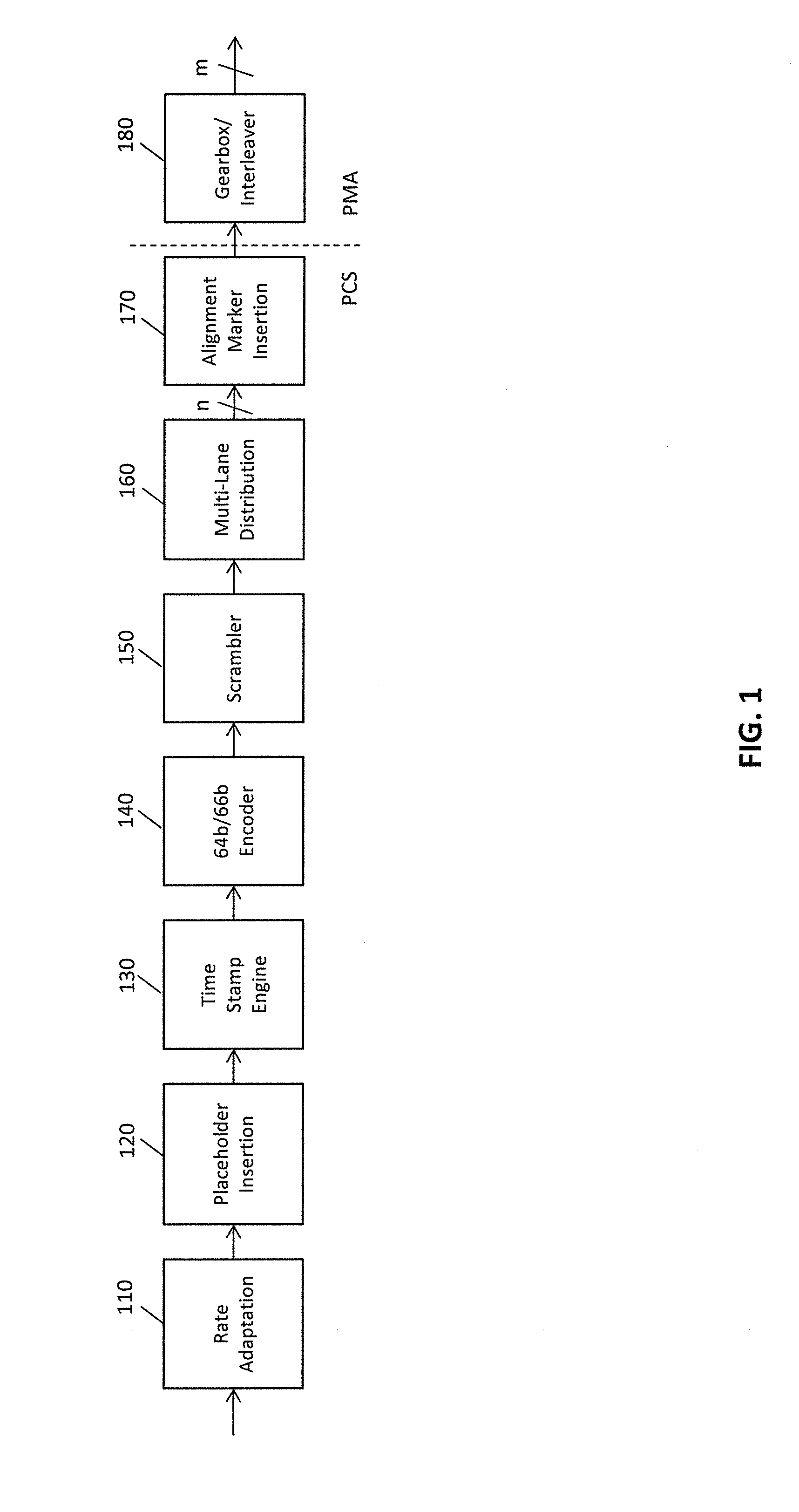
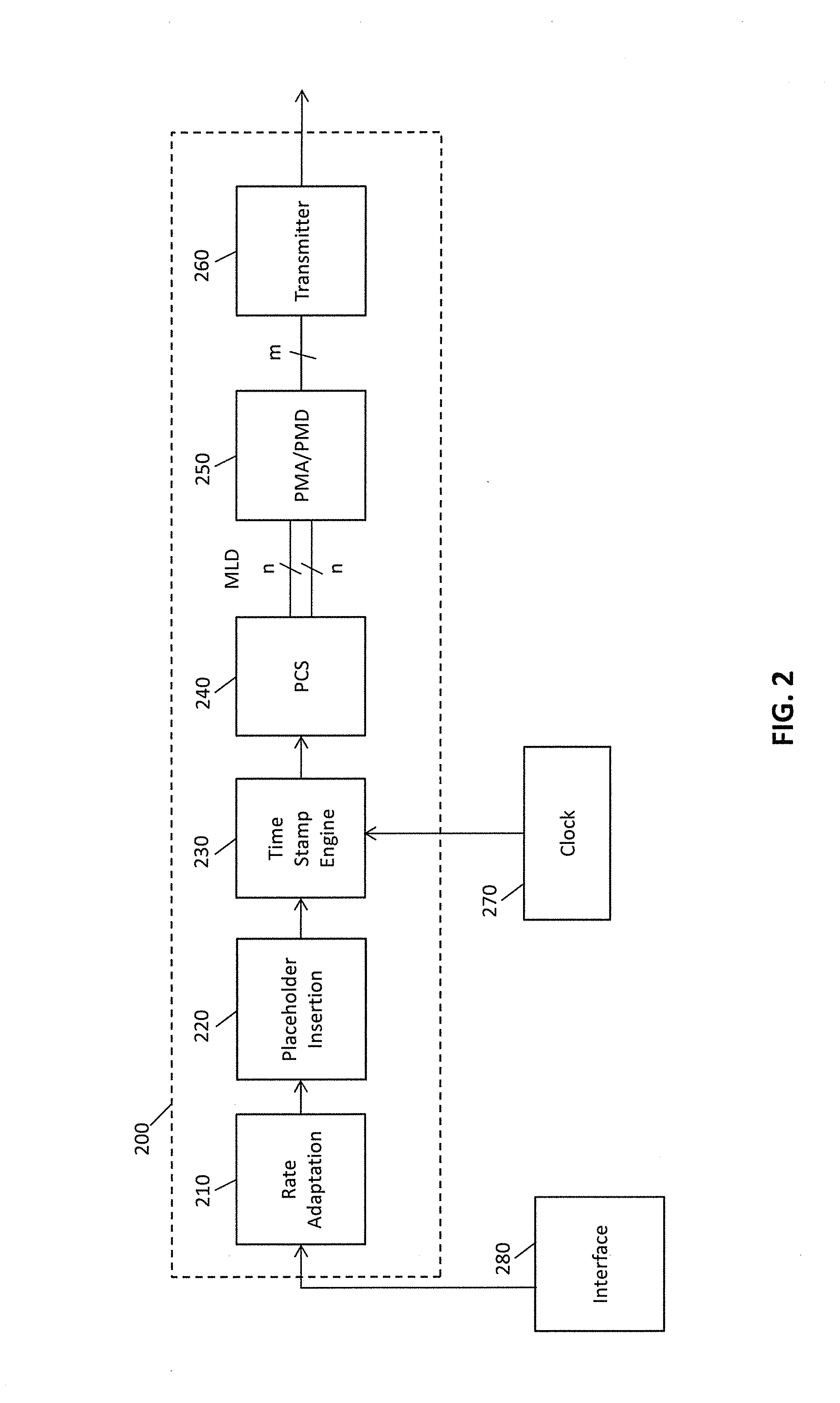
This patent describes methods and devices for time stamping packets in a network. The invention allows for the adjustment of data rates and the insertion of placeholders for alignment markers in the data stream. The device also includes a timestamp engine to write timestamp values and a circuitry to distribute the data for transmission. The invention can be used in a network for ensuring the proper timing of data transmission and processing frames for MACSec. The technical effects of this patent are improved reliability and accuracy in network communications and the efficient management of data transmission and processing.

Problems solved by technology

Unfortunately, the path delay may not be symmetric in both directions, and variable latencies within any particular path may also result in variability in path delays.

Method used


Image

  • High accuracy 1588 timestamping over high speed multi lane distribution physical code sublayers
  • High accuracy 1588 timestamping over high speed multi lane distribution physical code sublayers
  • High accuracy 1588 timestamping over high speed multi lane distribution physical code sublayers

Examples


Embodiment Construction

[0018]For an Ethernet transmission device, a Physical Coding Sublayer (PCS) receives information from a Media Access Controller (MAC) or Reconciliation Sublayer (RS) of a data link layer, with the PCS providing the information to a physical medium attachment / physical medium dependent (PMA / PMD) Sublayer for transmission over a medium. The PCS performs various functions, for example 64 b / 66 b encoding and scrambling, with the PCS also including a multilane distribution (MLD) Sublayer, at least for particular Ethernet transmission devices. In some embodiments alignment markers are used to identify virtual lanes in a multilane distribution environment. As the PCS may operate at slightly different data speeds than a data link layer, rate adjustment or adaptation may be performed, generally through insertion or deletion of idle symbols.

[0019]In some embodiments of the invention the PCS performs time stamp functions for a precision packet timing protocol (PTP), for example 1588v2, with the...


PUM


Abstract

A physical layer device provides for synchronization of clocks in a communication network. A place holder for an alignment marker is inserted into a frame to be transmitted. Once the placeholder alignment marker is inserted into the frame, no additional data is added to the frame. Transmission of the frame including the placeholder alignment marker may also be delayed to allow data processing in subsequent blocks within a transmit block to complete prior to further processing of the frame including the placeholder alignment marker (e.g., timestamping, MACSec, etc.) to improve timing accuracy with a multi lane distribution environment.

Description

CROSS REFERENCE TO RELATED APPLICATIONS[0001]This application claims the benefit of the filing of U.S. Provisional Patent Application No. 61 / 707,679, filed on Sep. 28, 2012, the disclosure of which is incorporated by reference herein.BACKGROUND OF THE INVENTION[0002]The present invention is generally directed to synchronization of clocks, and more particularly to synchronization of clocks in a packet-switched communication network.[0003]Clock synchronization is important in many automated electronic systems. Many automated electronic systems use Ethernet as a communication medium because of its ease of installation and low cost. In such systems, it may be advantageous for devices in the network to have a common base time. The common base time may be used, for example, to trigger coordinated measurement instances in a network of sensors, to coordinate actions of controllers in an industrial system, or to synchronize clocks of mobile / cellular radio base stations. In addition to sensor...

Claims


Application Information

Patent Timeline
IPC IPC(8): H04J3/06
CPCH04J3/0661H04L25/14H04J3/0667H04J3/0697H04L43/106H04L1/0083
Inventor JOST, THOMAS
Owner MICROSEMI STORAGE SOLUTIONS
Learn More