Gamma radiation breast imaging apparatus

a breast imaging and gamma radiation technology, applied in the field of gamma radiation imaging apparatus, can solve the problems of insufficient accuracy of relative large fraction of images, discomfort or even pain of patients, and the number of images being taken is higher than the necessary number, so as to increase the range of angles and increase the surface area of the image. , the effect of preventing nois

Active Publication Date: 2014-04-03
MILABS BV
View PDF0 Cites 22 Cited by
  • Summary
  • Abstract
  • Description
  • Claims
  • Application Information

AI Technical Summary

Benefits of technology

[0049]In particular, the collimator may comprise a substantially flat or planar first collimator plate part and a substantially flat or planar second collimator plate joining the first collimator plate part and extending at a non-zero angle, preferably a substantially downward and perpendicular angle, to the first collimator plate part. Preferably said collimator, e.g. said second collimator plate part, comprises a third plurality of pinholes having a separate central field of view, distinct from the central field of view afforded by the first plurality and, when present, by the second plurality of pinholes of the collimator. While it is possible, as described further above, to use the a single collimator plate with a first plurality of pinholes for imaging both breast tissue and axillary tissue, it considered advantageous to use a dedicated and distinct set or plurality of pinholes for imaging said axillary tissue, preferably said additional set of axillary tissue imaging pinholes being positioned at or near a join of a first collimator plate part and a second collimator plate part, e.g. with at least one pinhole of said third plurality in said second collimator plate. One is then free to select the number of pinholes, their focus area and so on for optimum axillary imaging.
[0050]In embodiments, most importantly when the collimator has multiple pluralities of focussed pinholes, the apparatus further may comprise one or more pinhole shutter devices that are each configured to selectively open and close at least one of the pluralities of pinholes. By selectively opening and closing a plurality of pinholes, specific imaging onto the detector can be selected, thereby preventing noise from non-focused radiation, but also providing the possibility to use parts of the detector area for more than one plurality of pinholes. The later could easily arise for pinholes on different collimator plate parts. Another, very particular use of the pinhole shutter devices could be to emulate moving of the gamma camera with respect to the object to be imaged. By selectively opening only suitable shaped pinholes, one can emulate the movement of the (central) field of view through the subject, without actually having to move either the collimator / gamma camera as a whole or the subject.
[0051]In embodiments, the detector is arranged at an acute non-zero angle with the collimator or with a collimator plate part thereof, e.g. with the collimator having perpendicular first and second collimator plate parts and the detector at an incline with respect to each of said plate parts. This further allows to increase the range of angles, as such tilted arrangement of the detector with respect to the collimator—compared to the common parallel arrangement to a plate collimator—mimics increasing the surface area thereof. In the extreme case of the detector and the (extension of) the collimator touching, one has almost a flat measuring set-up. If the detector is supported so as to be tiltable with respect to the collimator, e.g. by a detector tilting device of the gamma camera, one can e.g. use a one-piece flat detector, which is easy to produce and versatile, with good use of all its surface area. This would not be possible in the prior art, as a symmetrical detector would mean a detector that is flat throughout, thus also in the middle. This in turn means no tilting, and thus no touching of the extension of the collimator. And though it would be possible to provide a two-part detector surface, with a bend in the middle to allow said touching with the extension of the collimator, such bend is highly undesirable, and certainly not useful for measuring.
[0052]In embodiments the collimator is selectively moveable horizontally and vertically, in each case along its associated positioning plate part when present. This allows to image the breast, and / or other tissue, to be imaged under different angles.
[0053]In an important embodiment, the breast positioning device is tiltable, such that at least the breast positioning members or plates are or can be arranged at an approximately 45° angle with respect to the vertical, e.g. when the subject is standing or sitting. Thereto, the apparatus may comprise a frame with a pivot mechanism, e.g. with horizontal pivot axis, with respect to which the one or more gamma cameras and positioning members are tiltable. This allows insertion, and imaging, of the tissue of (part of the) breast, and possibly of the armpit and tissue in-between. Of course, one may allow for adjustability of the tilting so that the exact angle with respect to the vertical may be dependent on the body of the subject.
[0054]In a suitable embodiment of the apparatus of the present invention the position of the members between which the breast is positioned is exactly known and the distance between pinholes and a breast lesion may be made very small, e.g. down to the thickness of one of the positioning plates, and of course the collimator and the desired distance, if any, between the collimator and the detector. The apparatus of the present invention may use this minimal distance by allowing to scan parallel to the very positioning plate that may contact the breast, or even compresses the breast to a certain degree. This small distance is a great advantage for image quality.

Problems solved by technology

Although this known apparatus has a relatively high accuracy and resolution, it suffers from the drawback that a relatively large fraction of the images are insufficiently accurate, for example showing an inaccurate location, or direction dependent blurring, of the tumor(s).
This can lead to an undesirably and unnecessarily high number of biopsies, tumor surgeries and breast amputations and also to a higher than necessary number of images being taken, which can cause discomfort or even pain to the patient, in particular to women of whom the breast is being imaged.
In addition it can lead to undetected small tumors or parts of tumors in which case no, or insufficient amounts of, tumor tissue will be removed by a surgeon.

Method used


Image

  • Gamma radiation breast imaging apparatus
  • Gamma radiation breast imaging apparatus
  • Gamma radiation breast imaging apparatus

Examples


Embodiment Construction

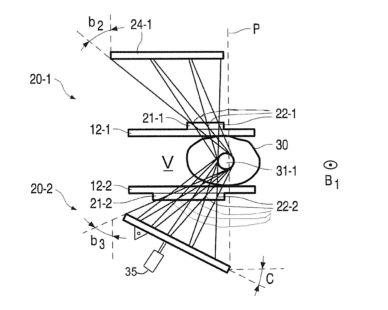
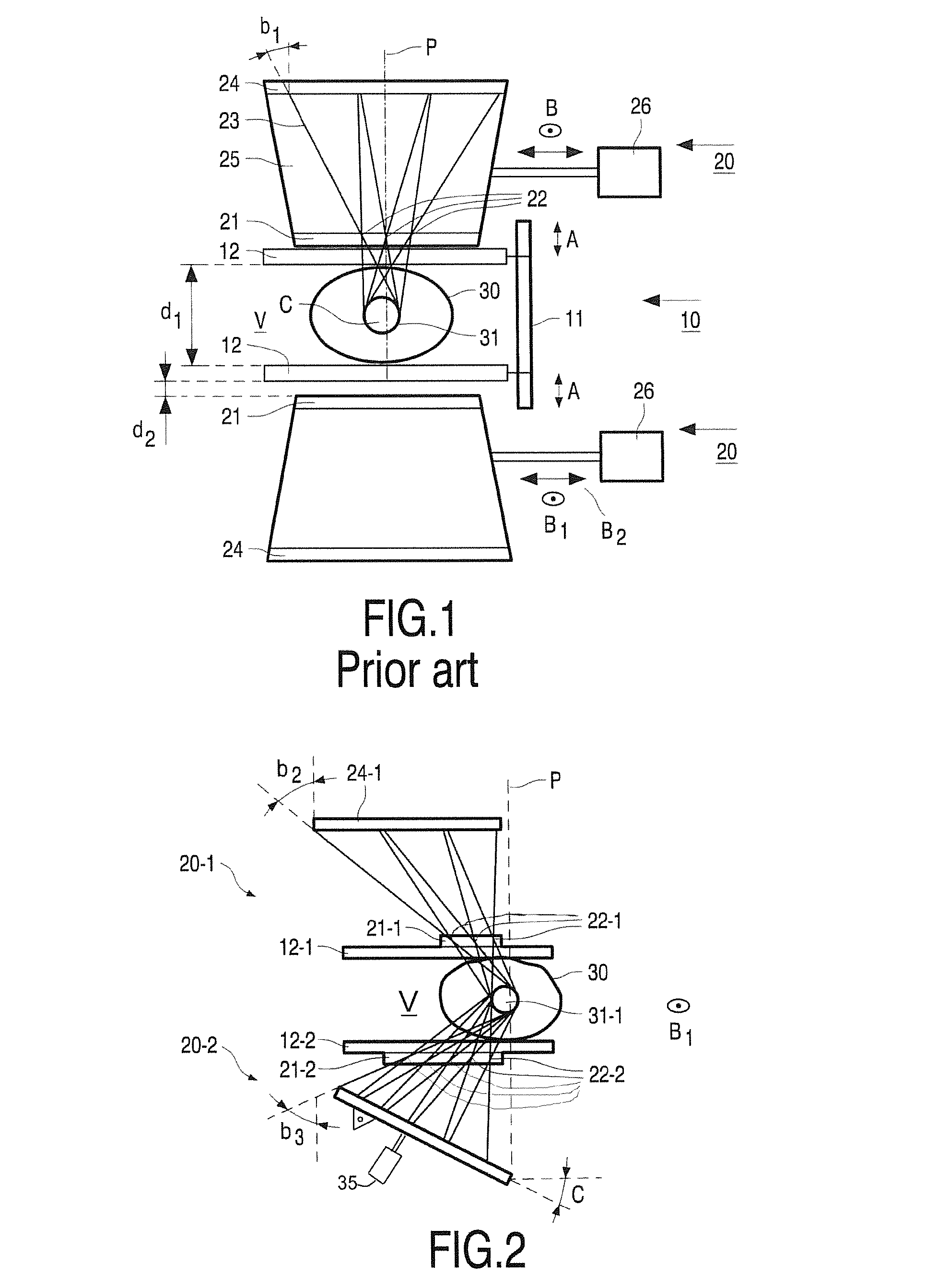
[0106]FIG. 1 shows diagrammatically an apparatus according to the prior art, in particular according to the cited document WO2010 / 014001, with a breast 30, a positioning device 10, and two gamma cameras 20-1, 20-2 generally above and below the breast to be imaged.

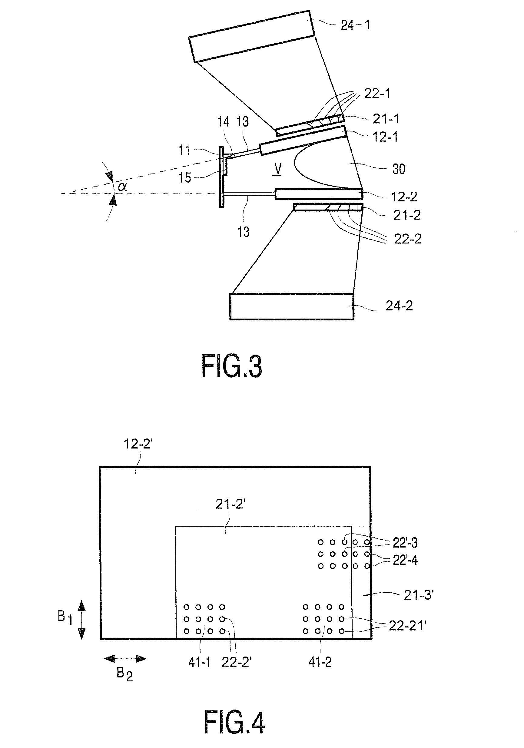
[0107]It is noted that one or more parts present in this prior art apparatus may, and preferably are, also present in the apparatus according to the invention, albeit sometimes in a modified form. Thus, for reasons of avoiding repetition, it is hereby assumed that a part or parts indicated in FIG. 1 or discussed with reference to FIG. 1 but not show or discussed with reference to all the other figures may be present therein as well.

[0108]Now turning to FIG. 1. The object or breast positioning device 10 comprises a frame 11, e.g. a frame to be placed on the floor of an exam room. The frame 11 supports two positioning members, embodied as plates 12, as is shown in a mutually parallel orientation, as is shown and practically s...


PUM


Abstract

A gamma radiation breast imaging apparatus, comprising an object positioning device, defining an imaging space and having as an intended insertion direction of the breast to be imaged, and a gamma camera positioned to image a volume in said imaging space. The gamma camera comprises a collimator with a first plurality of focused pinholes, the individual fields of view of the first pinholes defining a common central field of view having a geometrical centre. The apparatus also has a gamma sensitive detector to receive images from the collimator. The first pinholes are provided non-symmetrically with respect to a first plane through said geometrical centre that is perpendicular to the collimator and parallel to said intended insertion direction. Hereby, more angular information about the scanned volume can be obtained for the same detector size, in particular when combined with a similar opposite camera.

Description

CROSS REFERENCE TO RELATED APPLICATIONS[0001]This application claims the benefit of Netherlands Application No. NL 2009566, filed Oct. 3, 2013, the contents of which are incorporated herein by reference.FIELD OF THE INVENTION[0002]The present invention relates to a gamma radiation imaging apparatus, in particular for breast imaging.BACKGROUND OF THE INVENTION[0003]Document WO2010 / 014001 discloses a breast scanner comprising an object positioning device, which comprises a frame supporting at least two positioning members—embodied as positioning plates—defining between them an imaging space for a breast to be imaged of a subject and allowing for insertion of the breast to be imaged in an intended insertion direction of the breast to be imaged, wherein at least one of the positioning members is movably mounted to said frame in a first direction substantially towards another positioning plate of the at least two positioning members, and wherein the positioning members are arranged to co...

Claims


Application Information

Patent Timeline
Patent Type & Authority Applications(United States)
IPC IPC(8): A61B6/00
CPCA61B6/502A61B6/0435A61B6/06A61B6/4291G21K1/025G01T1/161
Inventor BEEKMAN, FREDERIK JOHANNES
Owner MILABS BV
Why Eureka
Try Eureka