
Hydraulic Fracturing Process for Deviated Wellbores

a hydraulic fracturing and wellbore technology, applied in drinking water installation, borehole/well accessories, construction, etc., can solve the problems of high cost of hydraulic fracture stimulation, high cost of hydraulic fracture equipment and wellbore intervention equipment, and high cost of use of isolation or diversion means at each stage, so as to improve the volume of stimulated reservoirs

Inactive Publication Date: 2014-04-10
CNOOC PETROLEUM NORTH AMERICA ULC
View PDF5 Cites 49 Cited by
  • Summary
  • Abstract
  • Description
  • Claims
  • Application Information

AI Technical Summary

Benefits of technology

The invention is a method for preparing a hydrocarbon reservoir for production without using mechanical devices such as plugs or diverters to isolate previous frac intervals from current frac intervals. Instead, the method reduces the frequency of using these tools and eliminates the need for these tools in practical application. By using a continuous process with select fire type perforating devices and pressure differences / rock stress changes, the method allows for effective preparation of the hydrocarbon reservoir for hydrocarbon production while reducing the time-consuming process of fracturing operations.

Problems solved by technology

The cost of stimulating production from horizontal wellbores often requires hydraulic fracture stimulation for the well to be commercial.
The cost of hydraulic fracture equipment and wellbore intervention equipment required for these operations are often based on the amount of time the equipment is on location regardless of whether the equipment is in use.
The operations performed during this time are often wellbore preparation such as setting plugs and perforating the pipe while the fracturing equipment is shut down and nonproductive.
The use of isolation or diversion means at each stage is costly, both financially and temporally.
It is known that the removal of a plug is more expensive than the setting of the plug.
The time involved in drilling out the plugs is also costly.
Furthermore, the use of diesel fuel or other hydrocarbon energy sources used to drive pumps and machinery during drilling operations to remove the plugs and the associated waste may have a negative impact on the environment.
Some of the costs associated with the prior art processes include (but are not limited to): cost of setting a bridge plug; cost of the bridge plug; cost of drilling out bridge plugs; cost of surface equipment; cost of fluids pumped plus expendables such as bits motors etc.

Method used


Image

  • Hydraulic Fracturing Process for Deviated Wellbores
  • Hydraulic Fracturing Process for Deviated Wellbores
  • Hydraulic Fracturing Process for Deviated Wellbores

Examples


example

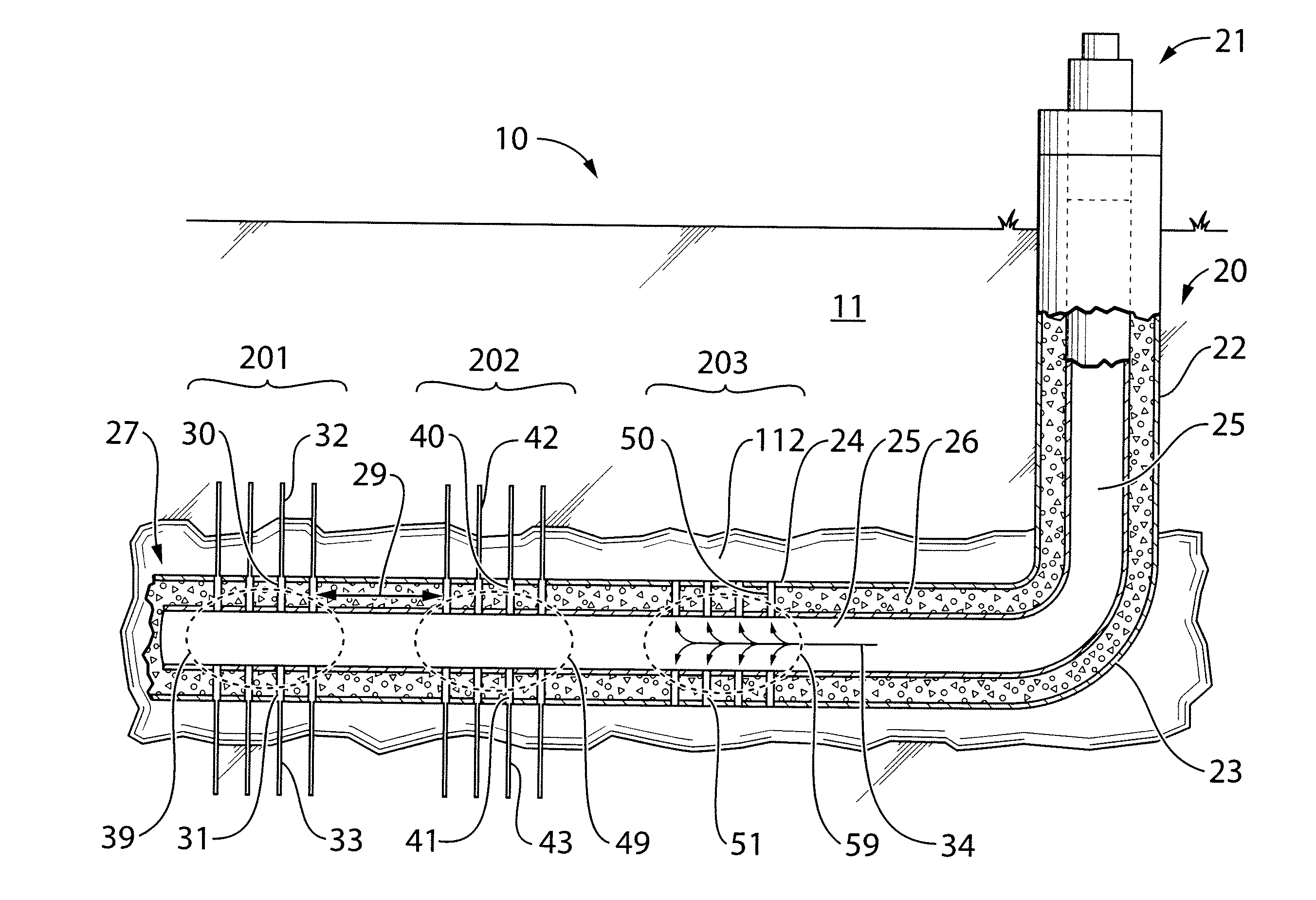
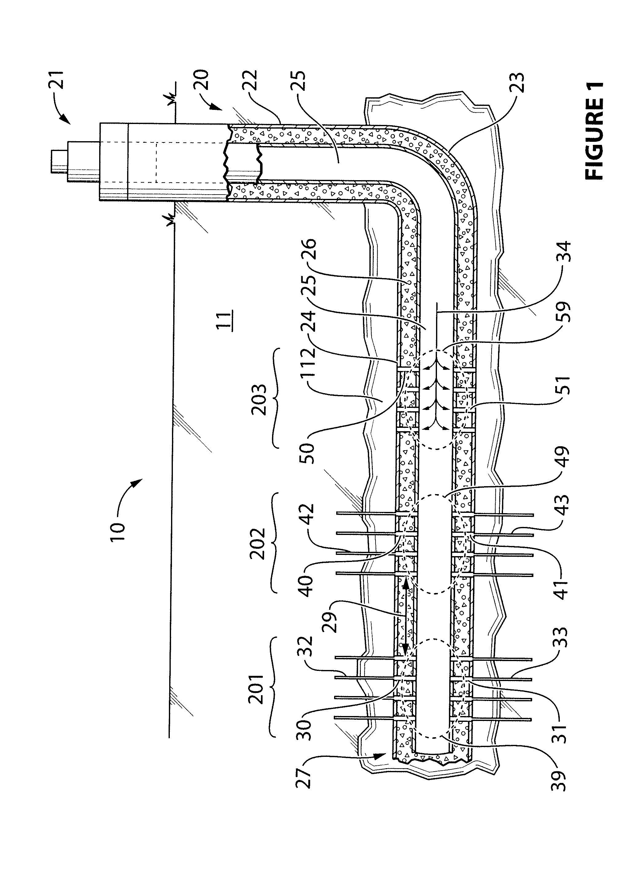
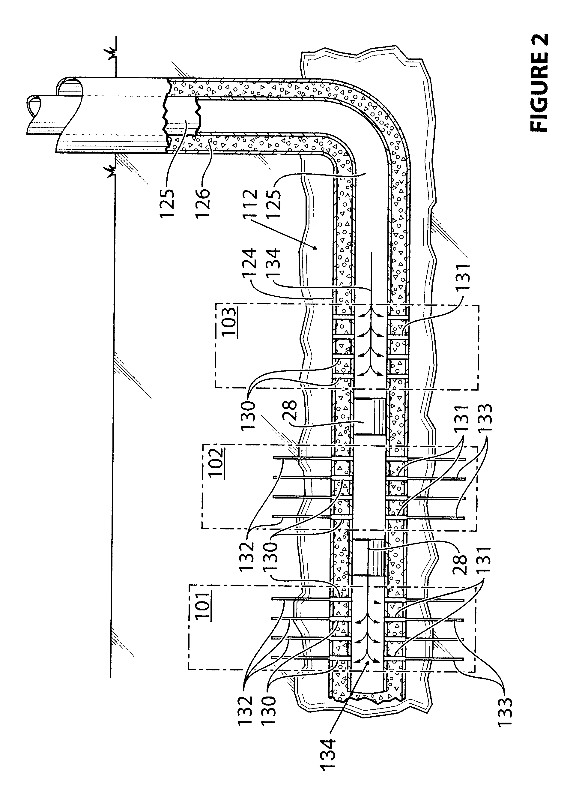
[0149]In the following example, traditional “Plug and Perf” was performed, followed by the method of the present invention, in a horizontal wellbore with a casing, to assess the viability thereof. Referring now to FIG. 4, the following was conducted:

[0150]Stages 101, 102, 103 up to 300 were created using the prior art technology “Plug and Perf” and then fractured with use of a plug 28 between each of the stages.

[0151]Upon completion of fracturing stage 300, a plug 28 was introduced into the wellbore 124. Wellbore 124 has a casing 125 which is cemented 126. Stage 201 was perforated 230 and 231 and fractured 232 and 233, followed by the perforation 241, 240, 251, 250 and fracturing 242, 243, 252, 253 of stages 202 and 203. R / A tracer was pumped (not shown) in stages 202 and 203 during fracturing. Three tracers were used: 1 Isotopes in test stage 202 and 2 Isotopes in test stage 203. A finding of 2 Isotopes of R / A material in these stages, indicated perforations in all stages and confi...


PUM


Abstract

A method of stimulating an interval in a hydrocarbon reservoir equipped with a deviated wellbore having a casing, wherein said interval comprises at least two sequential stages in said wellbore without isolation means, said method comprising:i) introducing a first stageii) introducing a second stage in the same wellborewherein said first stage, and second stage are not separated by any isolation means; and optionallyiii) recovering hydrocarbon from said hydrocarbon reservoir to a surface.

Description

FIELD OF THE INVENTION[0001]This invention is directed to a method of fracturing a plurality of stages, without the need of any isolation or diversion means, in a subterranean formation from a deviated wellbore penetrating a hydrocarbon containing formation.BACKGROUND OF THE INVENTION[0002]In the production of hydrocarbons from subterranean rock formations penetrated by wellbores, a commonly used technique for stimulating such production is to create and extend fractures in the formations. Most often, the fractures are created by applying hydraulic pressure to the subterranean formations from the wellbores penetrating them. That is, a fracturing fluid or a combination of fluids are pumped through the wellbore and into a formation to be fractured at a rate and pressure such that the resultant hydraulic pressure exerted on the formation causes one or more fractures to be created therein and / or extends any existing fractures (natural or otherwise) in the formation. The fractures are ex...

Claims


Application Information

Patent Timeline
IPC IPC(8): E21B43/26
CPCE21B43/26E21B43/263E21B43/2605
Inventor PYECROFT, JAMES FREDERICKCHERNIK, PETER
Owner CNOOC PETROLEUM NORTH AMERICA ULC
Learn More