
Integrated Two Dimensional Robotic Palm for Variable Pitch Positioning of Multiple Transfer Devices

a two-dimensional robotic palm and variable pitch technology, applied in the direction of manipulators, gripping heads, load-engaging elements, etc., can solve the problems of plant downtime and require multiple tooling

Active Publication Date: 2014-04-10
FESTO CORPORATION
View PDF3 Cites 5 Cited by
  • Summary
  • Abstract
  • Description
  • Claims
  • Application Information

AI Technical Summary

Benefits of technology

The present invention relates to a handling device that can move in different directions. The device includes a base plate, X rails, Y rails, and a drive system for moving the rails. The spacing between the rails can vary as the rails move. The device also includes a sliding puck assembly and a transfer device for manipulating work. The sliding puck assembly and transfer device allow for precise positioning of the rails. The drive system can include a single actuator or a combination of actuators for moving both the X and Y rails. The device can be used in various applications such as robotic palm handling.

Problems solved by technology

This may result in plant downtime and may also require multiple tooling.

Method used


Image

  • Integrated Two Dimensional Robotic Palm for Variable Pitch Positioning of Multiple Transfer Devices
  • Integrated Two Dimensional Robotic Palm for Variable Pitch Positioning of Multiple Transfer Devices
  • Integrated Two Dimensional Robotic Palm for Variable Pitch Positioning of Multiple Transfer Devices

Examples


Embodiment Construction

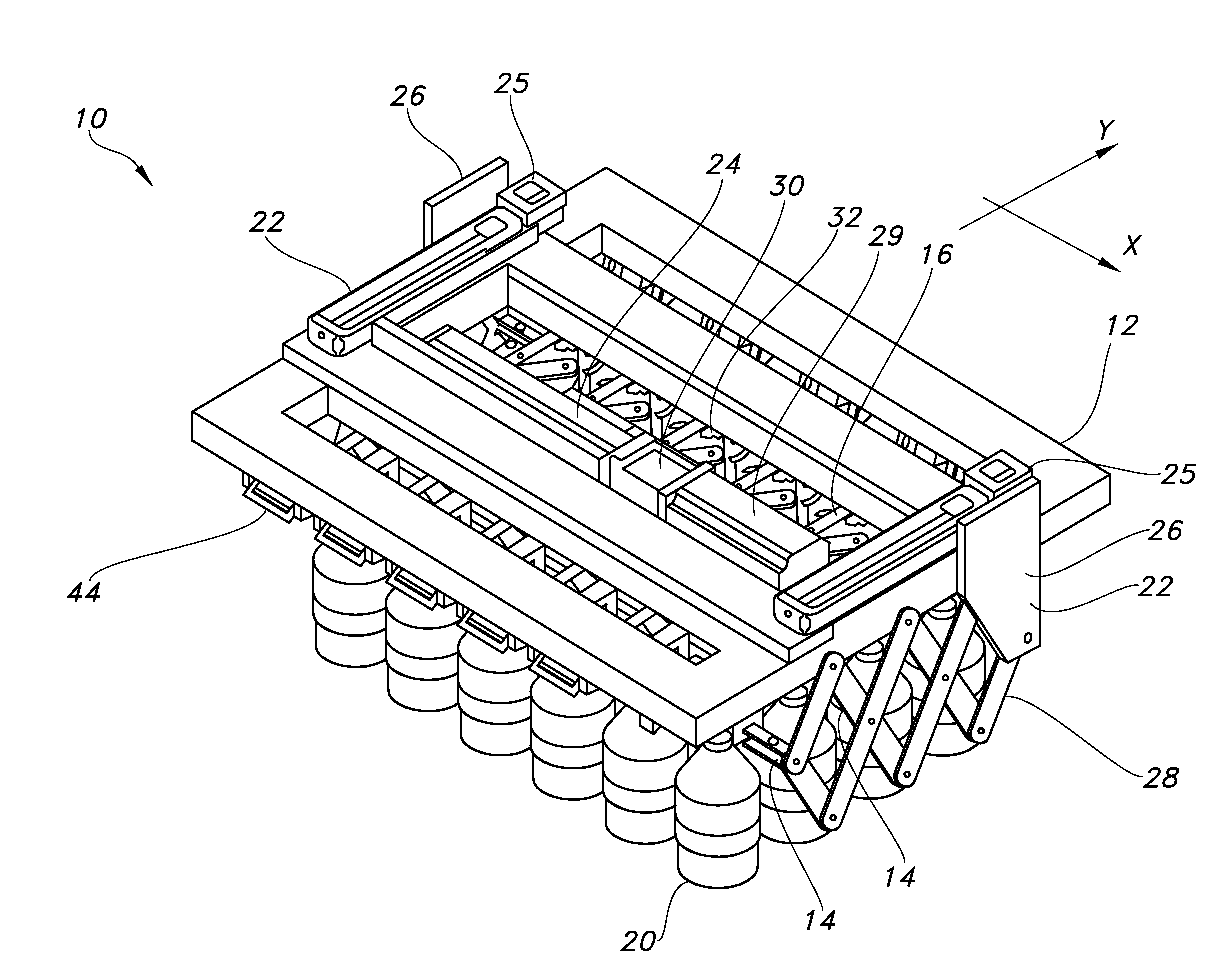
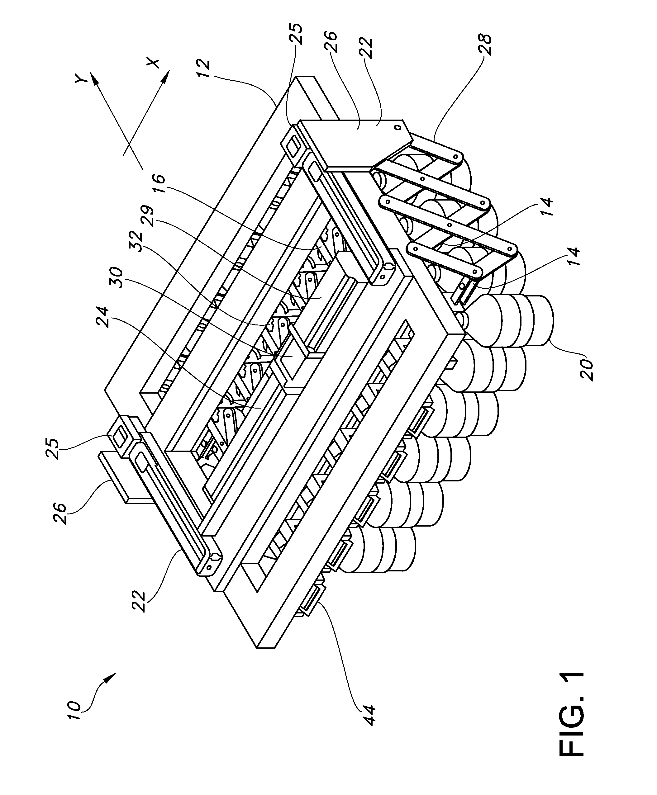
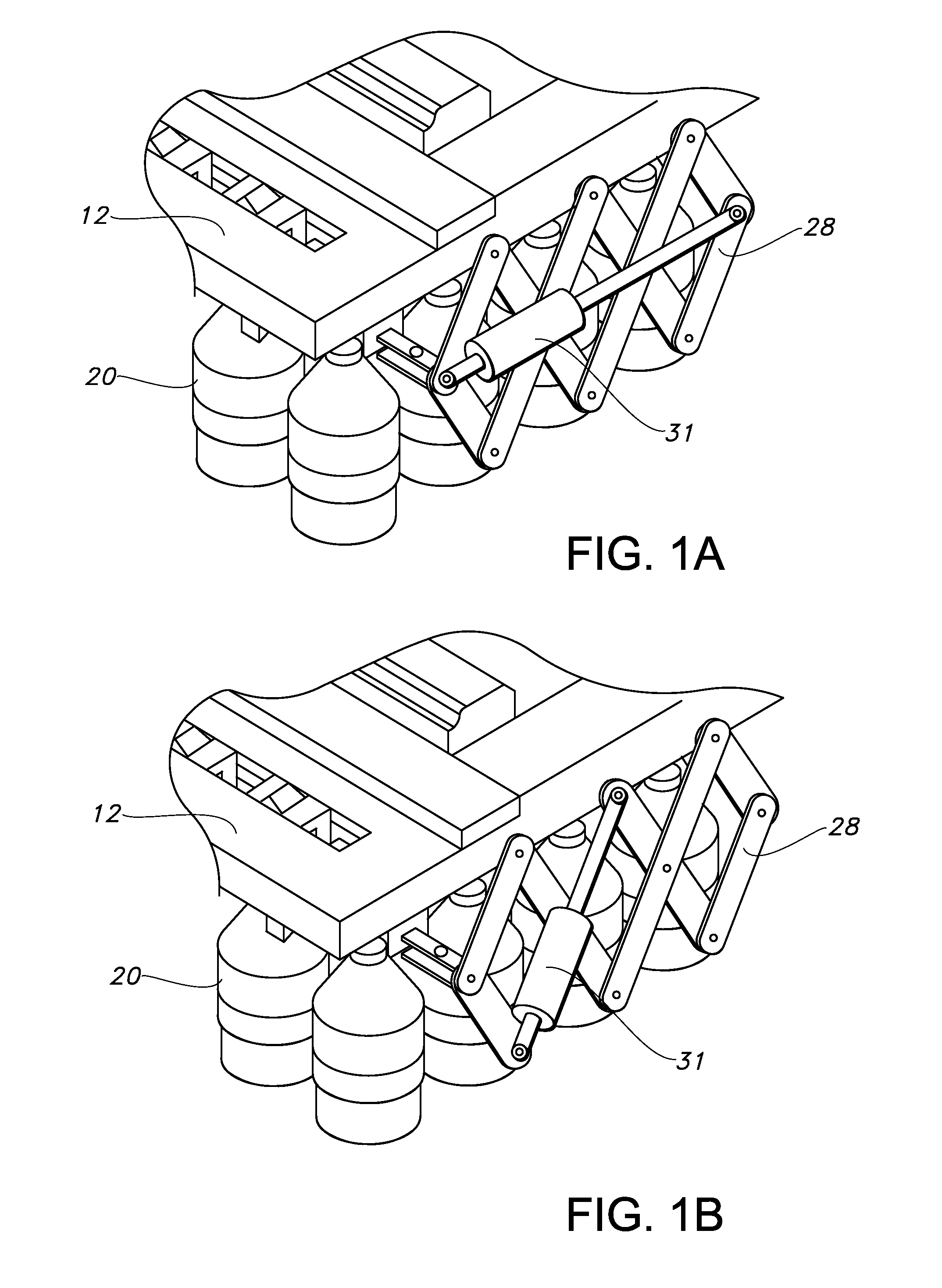
[0048]A two dimensional robotic palm handling device 10 of the present invention is shown in FIGS. 1-3. It should first be noted that in the following description the term “X rail” will be used to describe linear rail elements that extend in or are parallel to the X direction and the term “Y rail” will be used to describe linear rail elements that extend in or are parallel with the Y direction according to the X and Y axis shown in the drawings. The terms “X stage,”“X scissors” and “X slides” will be used to describe elements or components that move in the X direction and the terms “Y stage,”“Y scissors” and “Y slide” will be used to describe elements or components that move in the Y direction according to the X and Y axis shown in the drawings. It can be appreciated that the X and Y directions can be oriented in a different manner, whereby the X and Y terms will be reversed. The following description is made by a way of example such that any person which is familiar with the art ca...


PUM


Abstract

A handling device includes a base plate defining an X-Y plane, a plurality of X rails movably supported on the base plate and extending in an X-direction, a plurality of Y rails movably supported on the base plate and extending in a Y-direction perpendicular to the X-direction and a drive system supported on the base plate for moving the X rails in the Y-direction and for moving the Y rails in the X-direction, wherein a spacing between the X rails varies as the X rails move, and wherein a spacing between the Y rails varies as the Y rails move, and wherein the spacing between the X-rails is continuously variable with respect to the spacing between the Y rails.

Description

CROSS-REFERENCE TO RELATED APPLICATIONS[0001]This application claims the benefit of U.S. Provisional Application No. 61 / 708,127, filed on Oct. 1, 2012, the specification of which is incorporated by reference herein in its entirety for all purposes.BACKGROUND[0002]The present invention relates generally to automated handling systems and, more particularly, to a two dimensional robotic palm handling device providing variable spacing in the X and Y direction for a matrix of grippers.[0003]Automated handling systems typically consist of three major high level parts: i) Robot; ii) Work; and iii) Tool. The robot could be any mechanical manipulator, (servo-controlled or manually assist), which can position a tool at a point within the robot working area in a desired orientation. Robots are applied in factory automation in many manipulation configurations, such as Cartesian, articulating, scara, tripods, hexapods, gantry.[0004]The Work may be any product which is being worked on during manu...

Claims


Application Information

Patent Timeline
Patent Type & Authority Applications(United States)
IPC IPC(8): B66C1/00
CPCB66C1/00B25J15/0061
Inventor EIDELBERG, BOAZPILOCK, THOMASQUIGLEY, MATTHEWHARAN, PATRICKFAIZULLABHOY, MUSTANSIR
Owner FESTO CORPORATION
Learn More