Loading/unloading robot

a robot and robot arm technology, applied in the field of loading/unloading robots, can solve the problems of long recovery time for the conveying robot, difficult to determine the operation has stopped midway, and little design freedom for the arm of the robot, and achieve the effect of simple revolution operation, simple loading and operation

Active Publication Date: 2014-04-10
HIRATA & CO LTD
View PDF2 Cites 1 Cited by
  • Summary
  • Abstract
  • Description
  • Claims
  • Application Information

AI Technical Summary

Benefits of technology

[0017]According to the present invention, when loading and unloading an object to be loaded and unloaded, it is possible to revolve the base portion by way of a simpler revolution operation, which means that loading and unloading can be carried out rapidly and it is simple to carry out operation control of the support unit by way of a revolution operation of the base portion. Since the arm unit is attached to the head portion, it is also simple to carry out operation control of the arm unit.

Problems solved by technology

Accordingly, there is little design freedom for the arm of a robot.
In addition, if the operation of a two-jointed arm that is making a complex operation has stopped midway, in many cases it will be extremely difficult to determine what operation has stopped midway, even when the stopped state is viewed.
Accordingly, with this type of conveying robot, if the operation stops for some reason, a long time will then be required for the conveying robot to recover.

Method used


Image

  • Loading/unloading robot
  • Loading/unloading robot
  • Loading/unloading robot

Examples


first embodiment

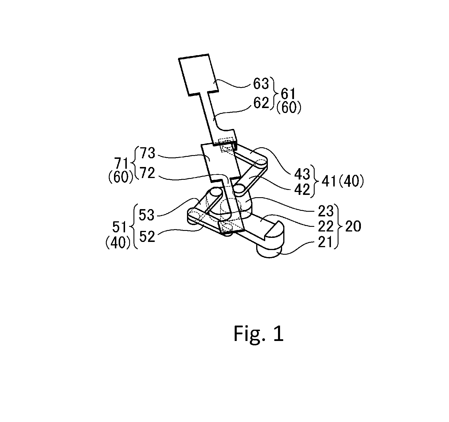
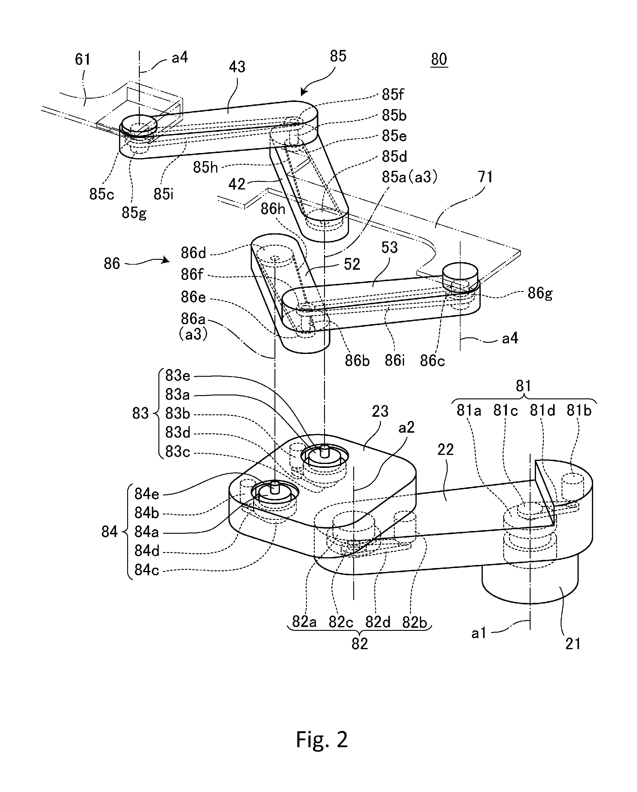
[0028]As shown in FIG. 1, the loading / unloading robot 10 according to the present embodiment includes a support unit 20 installed so as to be capable of being raised and lowered, an arm unit 40 (41, 51) attached to the support unit, and a hand unit 60 attached to the arm unit 40.

[0029]The support unit 20 includes a pillar portion 21 installed so as to be capable of being raised and lowered, a base portion 22 fixed to the pillar portion 21, and a head portion 23 attached to the base portion 22.

[0030]The pillar portion 21 is capable of being raised and lowered in the vertical direction and is also capable of rotating (revolving) around a vertical axis a1 of the pillar portion 21. When the pillar portion 21 is raised or lowered and rotates (revolves), the base portion 22 that is integrally fixed to the pillar portion 21 is also raised or lowered and rotates (revolves).

[0031]The base portion 22 extends horizontally from a rear portion fixed to the pillar portion 21 and at a front portio...

second embodiment

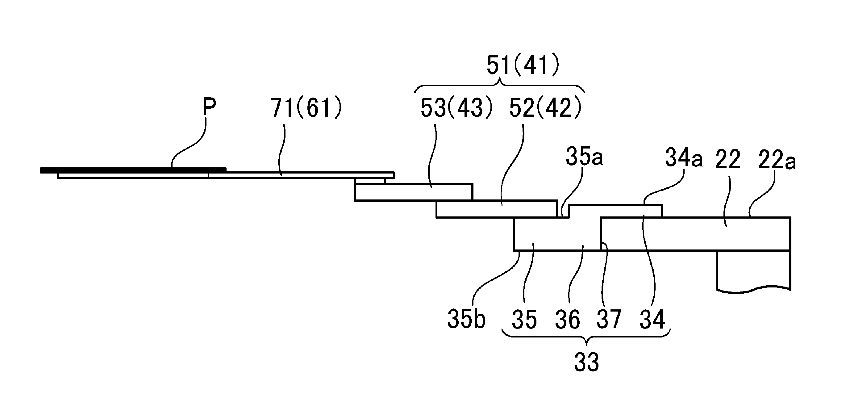
[0085]In the same way as the loading / unloading robot 10 according to the first embodiment, a loading / unloading robot 11 according to the present embodiment includes the support unit 20 installed so as to be capable of being raised and lowered, the arm unit 40 that is attached to the support unit 20, and the hand unit 60 that is attached to the arm unit 40, but differs to the loading / unloading robot 10 according to the first embodiment in the construction of the head portion (see FIG. 6). Since the remaining construction is the same as the loading / unloading robot 10 according to the first embodiment, detailed description of the head portion is omitted here. Constructions that are the same have been assigned the same reference numerals and description thereof is omitted.

[0086]As shown in FIG. 6, a head portion 33 of the loading / unloading robot 11 according to the present embodiment includes a base-end portion 34 rotatably supported on the base portion 22, a front portion 35 that rotat...


PUM


Abstract

A loading/unloading robot includes an arm unit attached to a support unit that is capable of being raised and lowered and a hand unit for conveying a loaded/unloaded object, attached to the arm unit. The support unit includes a base portion capable of revolving around a raising/lowering axis and a head portion rotatably attached to the base portion. The arm unit includes arms that are rotatably attached to the head portion. Front ends of the arms move forward and backward along a forward/backward direction that passes the head portion. The hand unit includes a loading/unloading hand rotatably attached to the arm. A center distance from the rotational axis of the head portion to the rotational axes of rear arms is shorter than a center distance from an axis of revolution of the base portion to the rotational axis of the head portion.

Description

FIELD OF THE INVENTION[0001]The present invention relates to a loading / unloading robot for conveying a material in the form of a thin plate (such as a panel, sheet, or wafer) which is a material of a digital device, and to a loading / unloading system equipped with a loading / unloading robot.DESCRIPTION OF THE RELATED ART[0002]One example of a loading / unloading robot is a wafer conveying robot (see Patent Document 1) including a support table capable of being raised and lowered, a first arm portion rotatably supported on the support table, a second arm portion rotatably supported on the first arm portion, an arm revolving mechanism incorporated into the first arm portion, two double-link arms provided on the second arm portion, and a double-link arm revolving mechanism incorporated into the second arm portion.[0003]Such wafer conveying robot has a construction where the double-link arm is mounted on the front end of a two-jointed arm of a SCARA (Selective Compliance Assembly Robot Arm)...

Claims


Application Information

Patent Timeline
Patent Type & Authority Applications(United States)
IPC IPC(8): B25J18/04B25J11/00
CPCB25J11/0095B25J18/04B25J9/043H01L21/67742H01L21/68707Y10S414/141
Inventor ANDO, HIROAKI
Owner HIRATA & CO LTD
Why Eureka
Try Eureka