Wide discourager tooth

a technology of disassembly and friction, applied in the direction of liquid fuel engines, machines/engines, mechanical apparatus, etc., can solve the problems of disadvantageous oil leakage across seals, thin air may not have enough force against the direction of oil seals, and the design of surrounding components

Active Publication Date: 2014-04-10
GENERAL ELECTRIC CO
View PDF8 Cites 19 Cited by
  • Summary
  • Abstract
  • Description
  • Claims
  • Application Information

AI Technical Summary

Benefits of technology

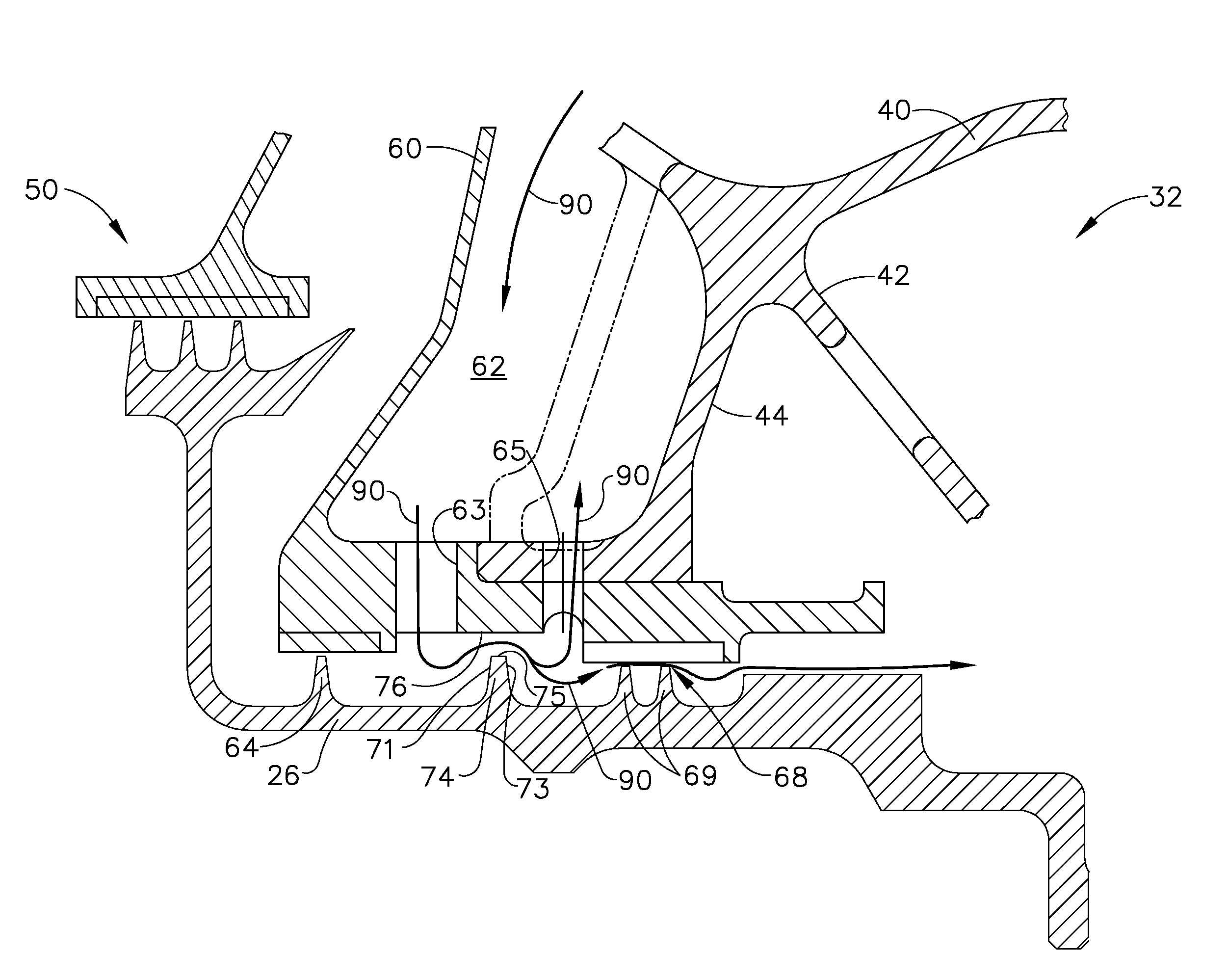
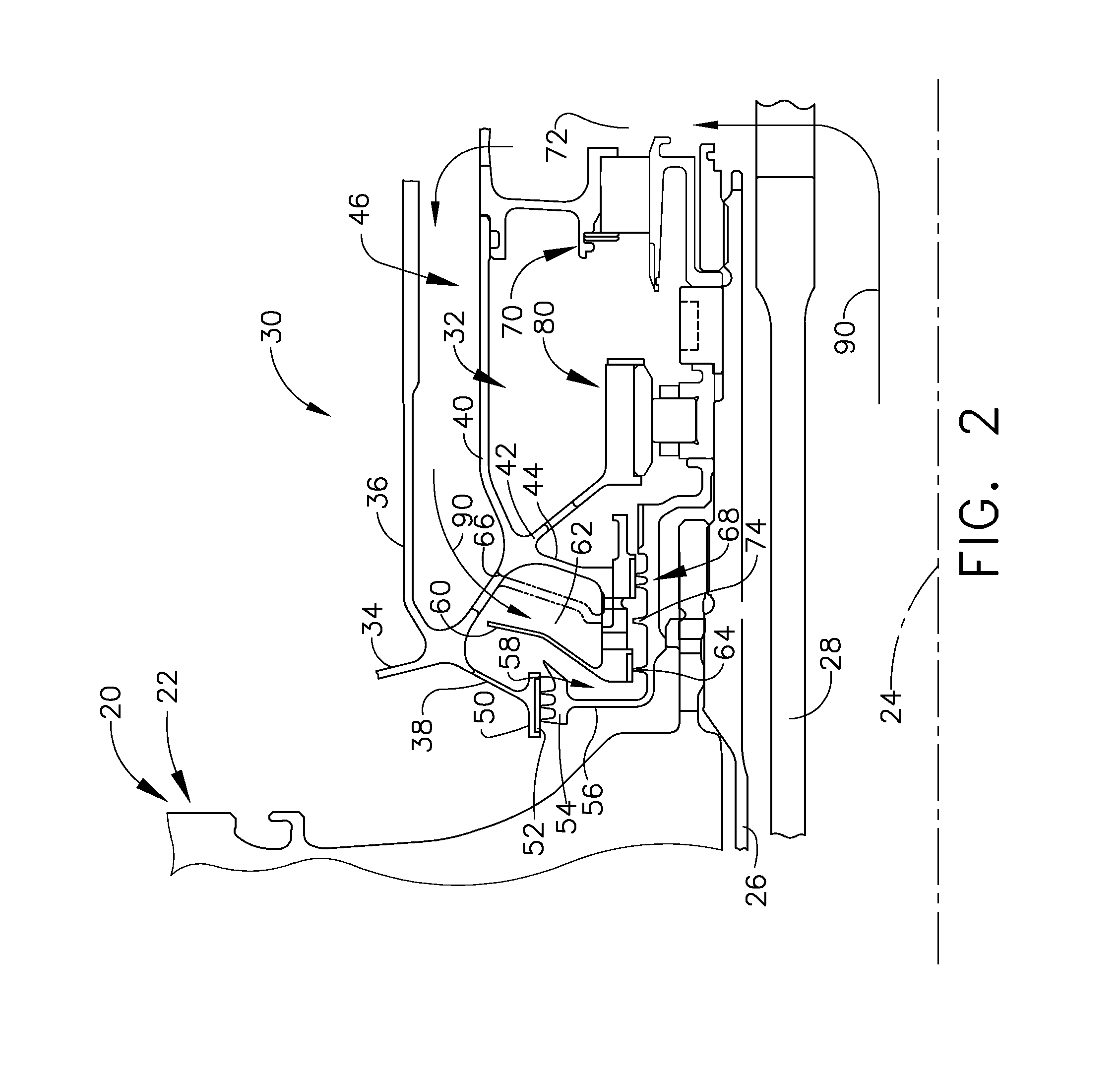
[0011]Some example embodiments according to at least some aspects of the present disclosure may involve an oil sump and the prevention of oil leakage from the sump, for example through a sump seal. Pressurized air flow may be directed through a pathway and over a widened discourager tooth. Some example widened discourager teeth may include a tip having an extended axial length for maintaining a design gap during axial excursions of the rotor shaft, to which the discourager tooth is connected. Some example widened discourager teeth may provide an elongated region of high velocity air flowing past, which may induce higher impulse. This higher impulse may approach oil particles which may have moved beyond an oil seal (e.g., a labyrinth seal) and may be more capable of changing oil particle direction to prevent oil leakage over the discourager tooth.

Problems solved by technology

Ensuring that a design gap over a discourager tooth is always maintained during these axial excursions often required extending the opposed sealing surface, which could be problematic to the design of surrounding components.
Such thin air may not have enough force against the direction of oil seals so as to fully inhibit leakage from the sump.
The problems: Oil leakage across seals may be disadvantageous for a turbine engine.
Axial excursions of the rotor and connected structures may cause an associated sealing structure to lose a design or seal gap with an opposed land.
In some oil sump configurations, excessive pressure differential around an oil sump may cause undesirable oil leakage.

Method used


Image

  • Wide discourager tooth
  • Wide discourager tooth
  • Wide discourager tooth

Examples


Embodiment Construction

[0021]In the following detailed description, reference is made to the accompanying drawings, which form a part hereof. In the drawings, similar symbols typically identify similar components, unless context dictates otherwise. The illustrative embodiments described in the detailed description, drawings, and claims are not meant to be limiting. Other embodiments may be utilized, and other changes may be made, without departing from the spirit or scope of the subject matter presented here. It will be readily understood that the aspects of the present disclosure, as generally described herein, and illustrated in the figures, can be arranged, substituted, combined, and designed in a wide variety of different configurations, all of which are explicitly contemplated and make part of this disclosure.

[0022]Reference now will be made in detail to embodiments provided, one or more examples of which are illustrated in the drawings. Each example is provided by way of explanation, not limitation ...


PUM


Abstract

Oil sump seal pressurization apparatus for turbine engines are disclosed. An example oil sump seal pressurization apparatus may include a non-rotating oil sump housing a bearing; an oil seal isolating an interior of the oil sump; a passage arranged to supply pressurization air to an outward side of the oil seal; a drain arranged to allow draining of oil and venting of at least some of the pressurization air, the drain being positioned axially between the passage and the oil seal; a wide discourager tooth disposed on the shaft and extending radially outward towards a non-rotating land, which may be disposed axially between the passage and the drain, the wide discourager tooth being spaced apart from the land in a radial direction by a gap, the wide discourager tooth including an upper surface; and / or an adjacent tooth disposed on the shaft and extending radially outward from the shaft.

Description

CROSS REFERENCE TO RELATED APPLICATION[0001]This application claims the benefit of U.S. Provisional Application No. 61 / 639,560, filed Apr. 27, 2012, which is incorporated by reference herein in its entirety.[0002]The subject matter of this application may be related to the subject matter of copending U.S. patent application Ser. No. ______, titled “MITIGATING VORTEX PUMPING EFFECT UPSTREAM OF OIL SEAL,” filed on even date herewith, which is incorporated by reference herein its entirety.BACKGROUND[0003]The subject matter disclosed herein relates generally to apparatuses and methods for retaining fluid lubricant, such as oil, in an oil sump and / or its drain path. More specifically, but not by way of limitation, some example embodiments relate to apparatuses and methods for maintaining design gaps during axial excursions of a shaft while also improving the limitation of oil leakage, for example from in a sump of a turbine engine.[0004]In a turbine engine, air is pressurized in a compre...

Claims


Application Information

Patent Timeline
Patent Type & Authority Applications(United States)
IPC IPC(8): F01D25/18
CPCF01D25/183F01D25/18F01D25/20
Inventor BORDNE, CHRISTOPHER MARKANSTEAD, DUANE HOWARDLUZ, JAMES JOHN
Owner GENERAL ELECTRIC CO
Why Eureka
Try Eureka