

Methods for bonding substrates
- Summary
- Abstract
- Description
- Claims
- Application Information
AI Technical Summary
Benefits of technology
Problems solved by technology
Method used
Image

Examples
Embodiment Construction
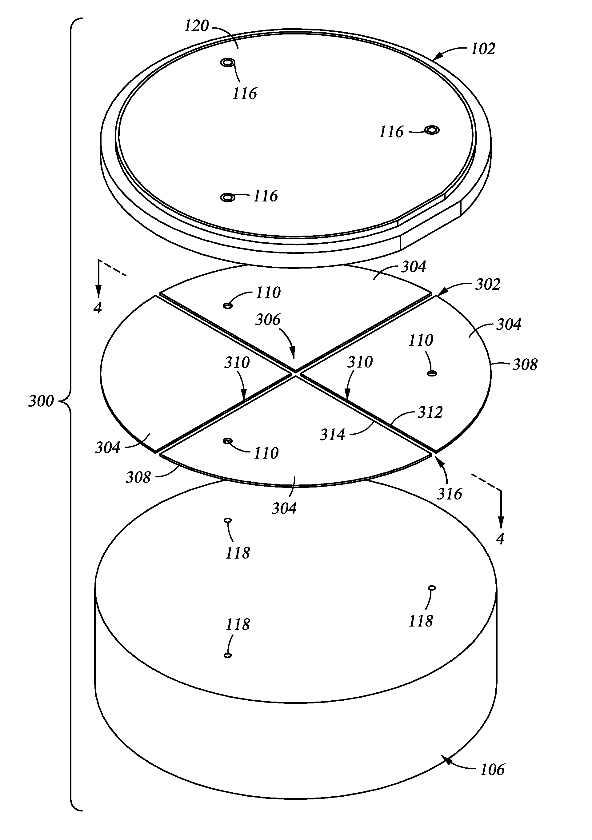
[0036]Embodiments of the invention generally provide a method for bonding substrates, assemblies fabricated by the same, along with improved methods for refurbishing said assemblies. Embodiments of the invention described herein take advantage of at least one channel partially bounded by an adhesive utilized to join two substrates. In certain embodiments of the invention, the channel is defined between adjacent segments of an adhesive layer bonding the substrates together. The channel is open to an exterior of the substrate assembly, thus providing a vent path for volatile gases outgassed from the adhesive layer to escape from between the substrates, either during curing or use of the assembly. Advantageously, the vent path enhances better curing of the adhesive layer. The vent path also prevents gas pockets from forming between the substrates which could adversely affect the temperature profile across the surface of the substrates. By improving reliability of the ability to control...
PUM
| Property | Measurement | Unit |
|---|---|---|
| Temperature | aaaaa | aaaaa |
| Tensile strength | aaaaa | aaaaa |
| Temperature | aaaaa | aaaaa |
Abstract
Description
Claims
Application Information