Electrical connector with carrier frame loading electronic package

Active Publication Date: 2014-04-10
HON HAI PRECISION IND CO LTD
View PDF2 Cites 0 Cited by
  • Summary
  • Abstract
  • Description
  • Claims
  • Application Information

AI Technical Summary

Benefits of technology

[0008]An object of the present invention is to provide an electrical connector having a carrier frame

Problems solved by technology

However, the exposed flexible mating portions may be broken, bent, or otherwise deformed w

Method used


Image

  • Electrical connector with carrier frame loading electronic package
  • Electrical connector with carrier frame loading electronic package
  • Electrical connector with carrier frame loading electronic package

Examples


Example

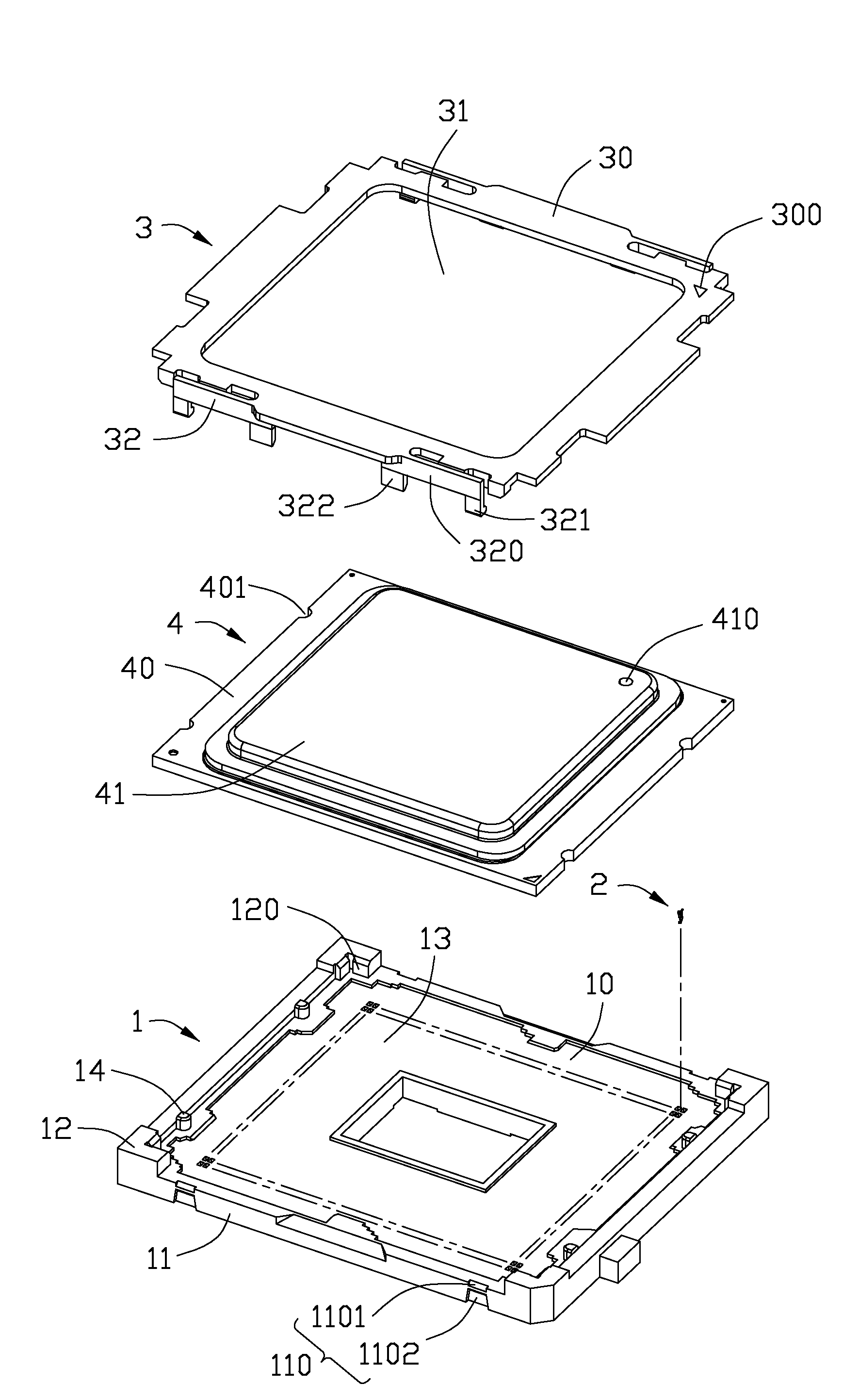
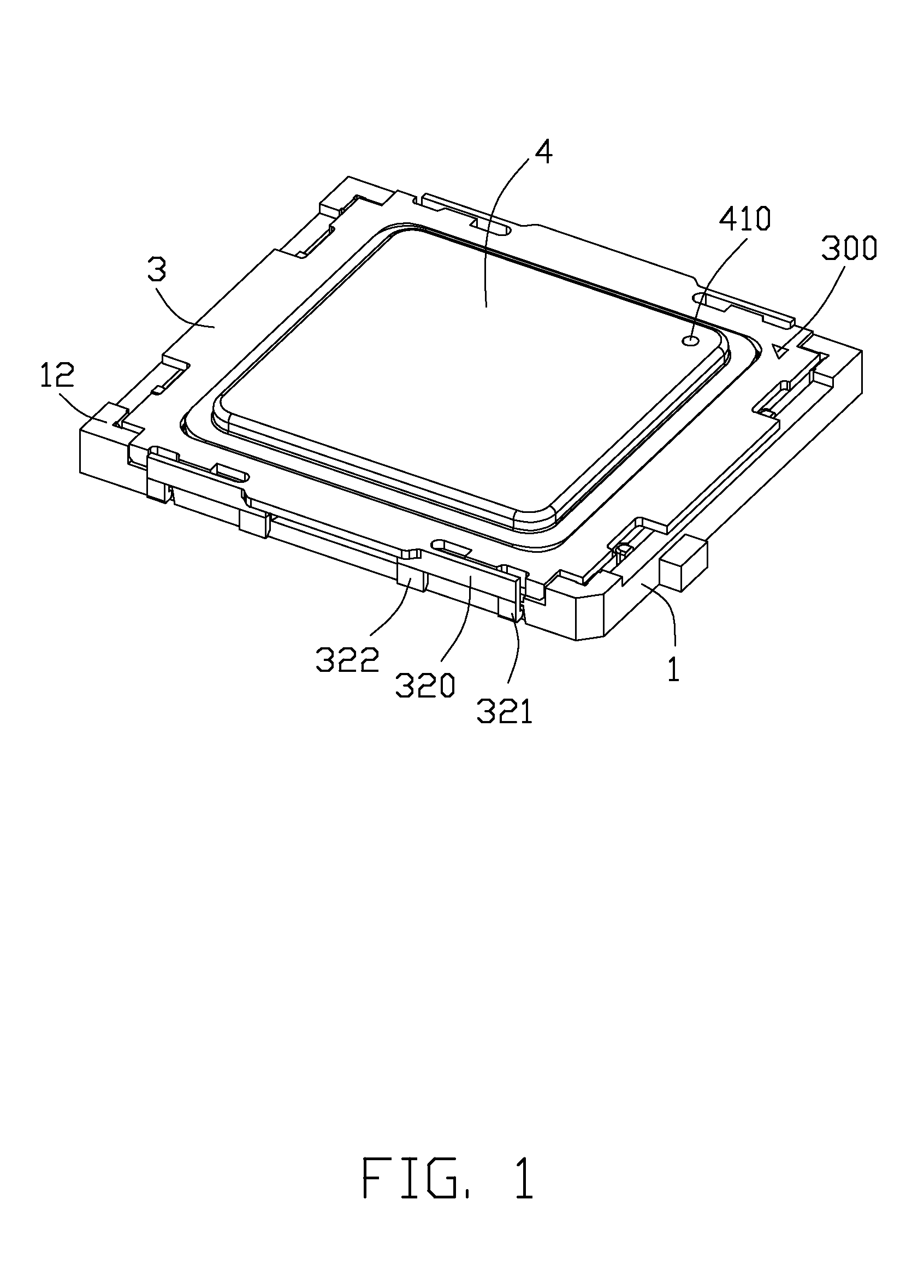
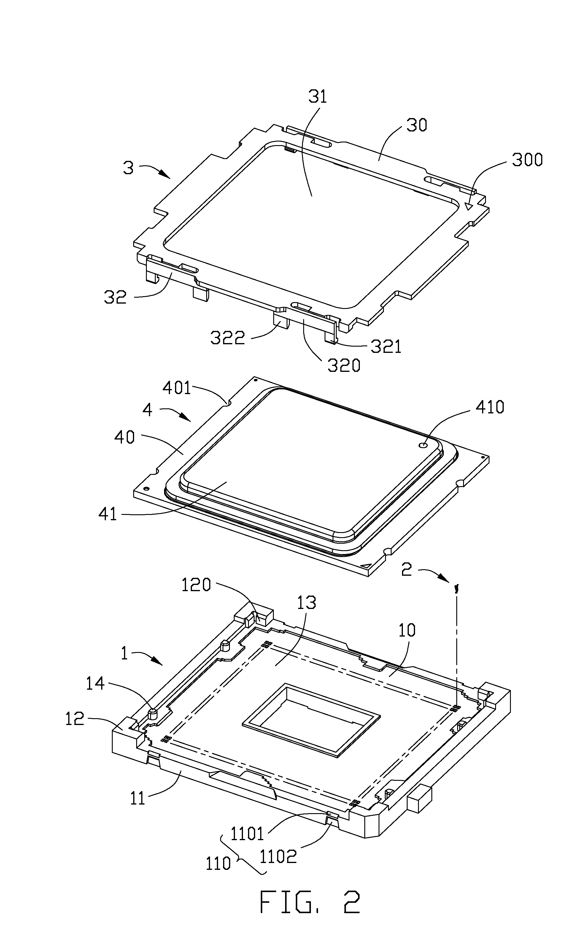
[0018]Referring to FIGS. 1 and 2, an electrical connector used for electrically connecting an electronic package 4 and a printed circuit board (PCB, not shown), comprises an insulative housing 1 with a plurality of contacts 2, a carrier frame 3 mounted to the insulative housing 1. The electronic package 4 includes a substrate 40 made with insulative material and a die 41 extending higher than the substrate 40.

[0019]The insulative housing 1 includes a base 10 for receiving the contacts 2. A plurality of sidewalls 11 defined by the base 10 has receiving portions 110 thereon to engage with the carrier frame 3. Each receiving portion 110 includes a chamfer 1101 located at top of the sidewall 11 and a recess 1102 located corresponding to the chamfer 1101 and lower than the chamfer 1101 at an up-to-down direction. Four bulges 120 protrude from corners of the base 10 and define a plurality of datums 120 to define a cavity 13 for receiving the electronic package 4. The contacts 2 are dispos...


PUM


Abstract

An electrical connector for use with an electronic package, includes an insulative housing defining an upward facing cavity, a plurality of contacts disposed in the cavity of the insulative housing with contacts sections extending into the cavity, and a carrier frame mounted to the insulative housing and having a main body defining an opening for allowing part of the electronic package passing through the opening. The carrier frame assembles to the insulative housing having a preliminary alignment state and a final alignment state.

Description

BACKGROUND OF THE INVENTION[0001]1. Field of the Invention[0002]The present invention relates to a electrical connector, and more particularly to the electrical connector having a carrier frame loading with an electronic package mounted to an insulative housing by straight downward moving so as to reduce damage to contacts assembled therein.[0003]2. Description of Related Art[0004]U.S. Pat. No. 7,001,197 issued to Shirai et al. on Feb. 26, 2006 discloses an electrical connector having an insulative housing with a plurality of contacts received therein. The contacts have mating portions extending beyond top surface of the insulative housing to contact with an electronic package. A cover member is pivotally mounted on a first end of the insulative housing. The cover member is pivotal between an open position and a closed position where the cover member presses the land grid array package toward the top surface of the insulative housing so that the land grid array package electrically ...

Claims


Application Information

Patent Timeline
IPC IPC(8): H01R24/28
CPCH05K7/1053
Inventor TERHUNE IV, ALBERT HARVEY
Owner HON HAI PRECISION IND CO LTD
Why Eureka
Try Eureka