Axially symmetrical Coriolis force gyroscope (variants)

a gyroscope and coriolis force technology, applied in the field of axial symmetrical coriolis force gyroscopes, can solve the problems of reducing the quality factor affecting the accuracy of the measured mode, so as to improve the technological effect of design, reduce the overall dimension, and reduce the size of the resonator

Active Publication Date: 2014-04-17
INNALABS
View PDF4 Cites 3 Cited by
  • Summary
  • Abstract
  • Description
  • Claims
  • Application Information

AI Technical Summary

Benefits of technology

[0008]The present invention aims to achieve a technical result that consists of decreasing the overall dimensions of an axisymmetrical Coriolis vibratory gyroscope, such as a cylindrical or hemispherical CVG, without employing the principle of reducing the size of the resonator. Moreover, the technical result also involves improvement of the technological effectiveness of the design, in particular by reducing the number of sealed leads in the base, which also increases the reliability of the gyroscope and makes it possible to reduce its size.

Problems solved by technology

They are widely used owing to their low price and compactness, but for several reasons their accuracy is inadequate (or difficult to achieve) for certain tactical and navigational purposes.
This leads to damping of the vibrations, i.e., decrease in the quality factor of the measured mode and correspondingly to an increase in the frequency range of the gyroscope.
Taking into account that MEMS gyroscopes cannot achieve high accuracy, or this is problematic, there is a need to reduce the size of CVGs with an axisymmetrical resonator of cylindrical or hemispherical shape.
However, with a large number of contacts (sealed leads), yet another restriction appears.
It should also be pointed out that as the number of metallic sealed leads increases, the cost of the gyroscope also increases, and its reliability decreases (owing to leakage of gas).

Method used


Image

  • Axially symmetrical Coriolis force gyroscope (variants)
  • Axially symmetrical Coriolis force gyroscope (variants)
  • Axially symmetrical Coriolis force gyroscope (variants)

Examples


Embodiment Construction

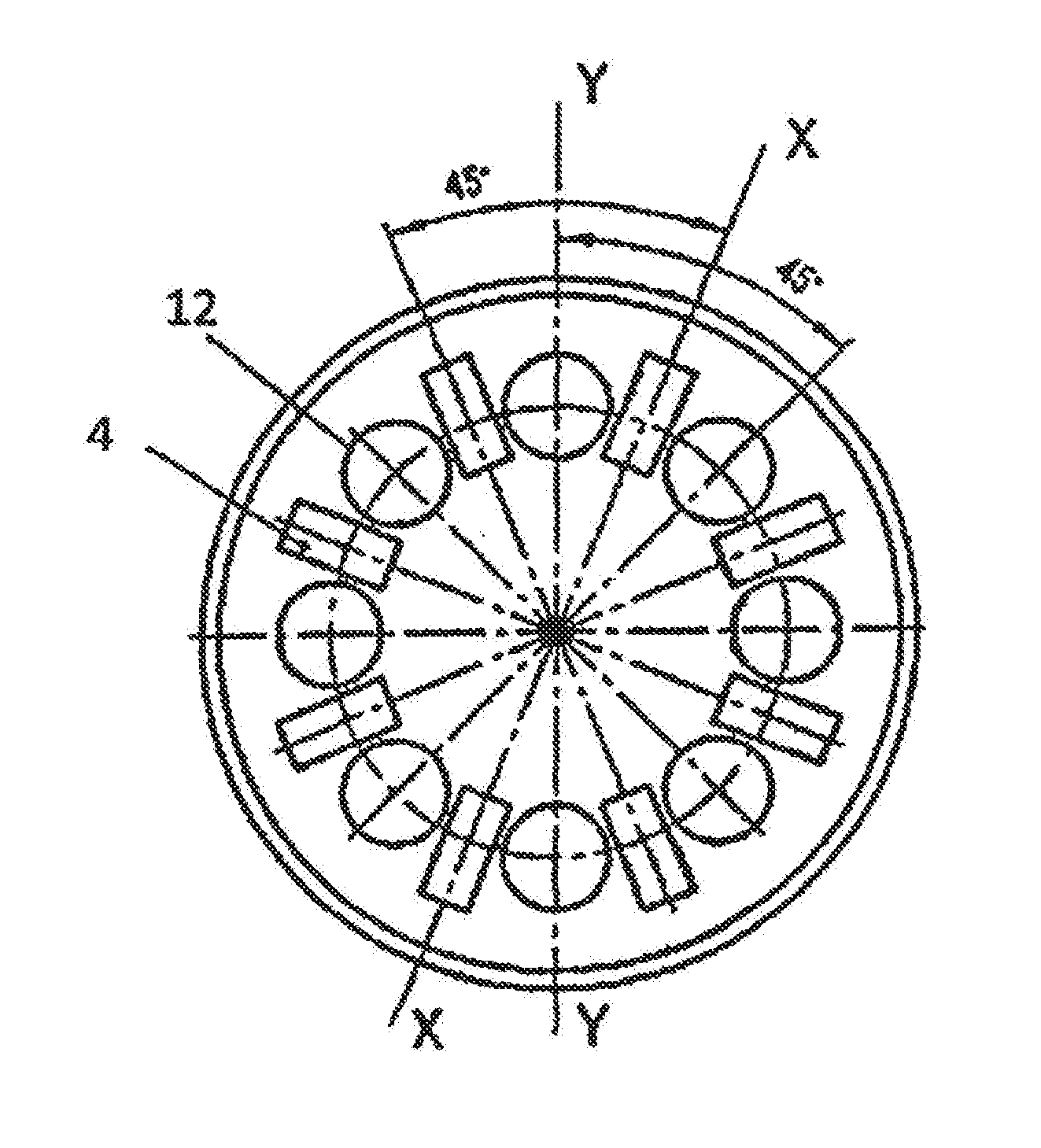
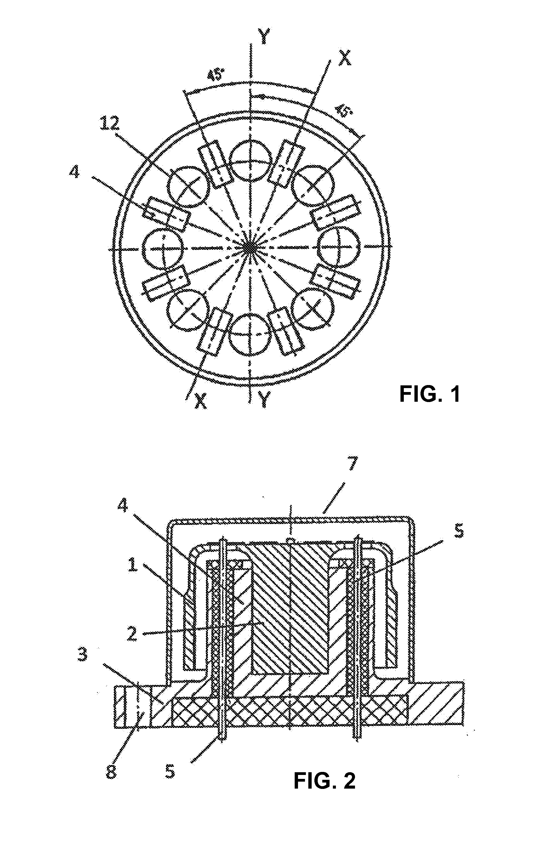
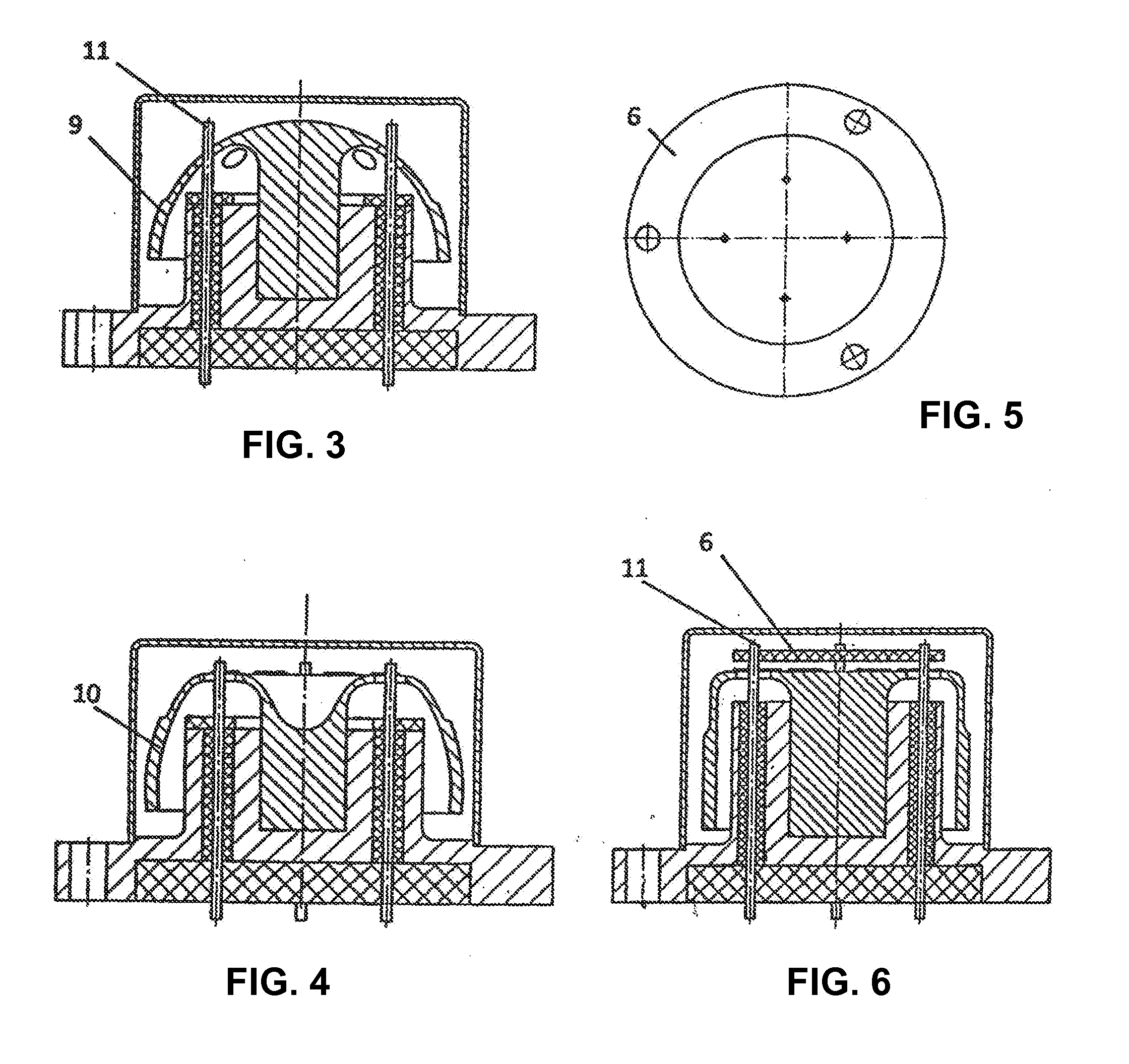
[0024]According to the present invention, the design of a compact axisymmetrical Coriolis vibratory gyroscope is examined, which comprises a thin-walled resonator of hemispherical or cylindrical or toroidal shape, fastened centrally on the stem and made with holes in the resonator wall, arranged around said stem, the number of which is determined from the formula “4nk”, where “k” is an integer, “n” is the order of the vibration modes, and the angle between two adjacent holes is equal to “π / 2nk”, moreover said stem is made symmetrical along its longitudinal axis and fastened on the base, solenoids and electrodes are arranged on the resonator wall or alongside it for excitation and measurement of two vibration modes, the constant amplitude of one of the modes of which is intended for monitoring a secondary vibration mode that is sensitive to Coriolis forces, and the base is made with a seating for the resonator stem and electrically-insulated sealed leads, led out through the base to ...


PUM


Abstract

The invention relates to gyroscope equipment. The axially symmetrical Coriolis vibratory gyroscope comprises a thin-walled resonator with a hemispherical or cylindrical or toroidal form, said resonator being fixed at the center to a support and being formed with openings in that wall of the resonator which is located around said support, the number of openings being determined on the basis of the formula 4nk, where k is an integer, n is the order of oscillation modes, and the angle between two neighboring openings is equal (I), wherein said support has a symmetrical form along the longitudinal axis thereof and is fixed to a base, solenoids and electrodes are positioned on the wall of the resonator or next to the resonator for exciting and measuring two oscillation modes, the constant amplitude of one of the modes thereof being intended for monitoring a secondary oscillation mode which is sensitive to Coriolis forces, and the base is provided with a seat for the support of the resonator and with electrically insulated hermetically sealed leads which pass outwards via the base and are passed through the openings in the wall of the resonator for connection to elements of an electronics board.

Description

FIELD OF TECHNOLOGY[0001]The invention relates to gyroscopic instrument engineering and can be used for measuring angular velocities and rotation angles relative to inertial space within systems for orientation, navigation and control of motion. The invention relates to Coriolis vibratory gyroscopes and in particular to axisymmetrical gyroscopes based on cylindrical or hemispherical resonators.DESCRIPTION OF THE RELATED ART[0002]The gyroscope is an instrument for measuring or maintaining orientation. Gyroscopes are used inter alia in inertial navigation systems (INS), stabilization of terrestrial means of transport, aircraft, ships, optical guidance axes, position finding etc. Standard vibratory gyroscopes are described in the following U.S. Pat. Nos. 6,698,271, 7,120,548, 7,240,533, 7,216,525, 7,281,425, 5,597,955. CVG technology is preferable for use in inertial systems owing to its low cost, simple manufacture, reliability in comparison with gyroscopes of other types, such as rin...

Claims


Application Information

Patent Timeline
Patent Type & Authority Applications(United States)
IPC IPC(8): G01C19/56
CPCG01C19/56G01C19/5691
Inventor CHIKOVANI, VALERY VALERIANOVICHYATZENKO, YURII ALEKSEEVICH
Owner INNALABS
Why Eureka
Try Eureka