Parking brake device

Active Publication Date: 2014-04-17
KNORR-BREMSE SYST FUER NUTZFAHRZEUGE GMBH
View PDF6 Cites 31 Cited by
  • Summary
  • Abstract
  • Description
  • Claims
  • Application Information

AI Technical Summary

Benefits of technology

[0040]For more accurate and/or more rapid adjustment of the pressure in the abovementioned function 4 and in order to achieve an improvement in the monitoring of this function, further pressure sensors or pressure switches can be provided at the first and/or at the third port of the parking brake valve and/or at the outlet of the relay valve.
[0041]According to a development of the invention, an anti-compound function can also be provided, preventing the wheel brakes from being overloaded by superimposition o

Problems solved by technology

This also applies to failure of an e

Method used


Image

  • Parking brake device
  • Parking brake device
  • Parking brake device

Examples


Embodiment Construction

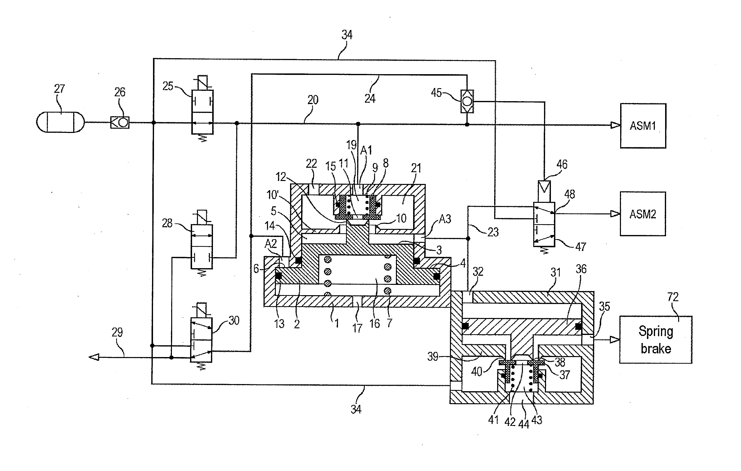
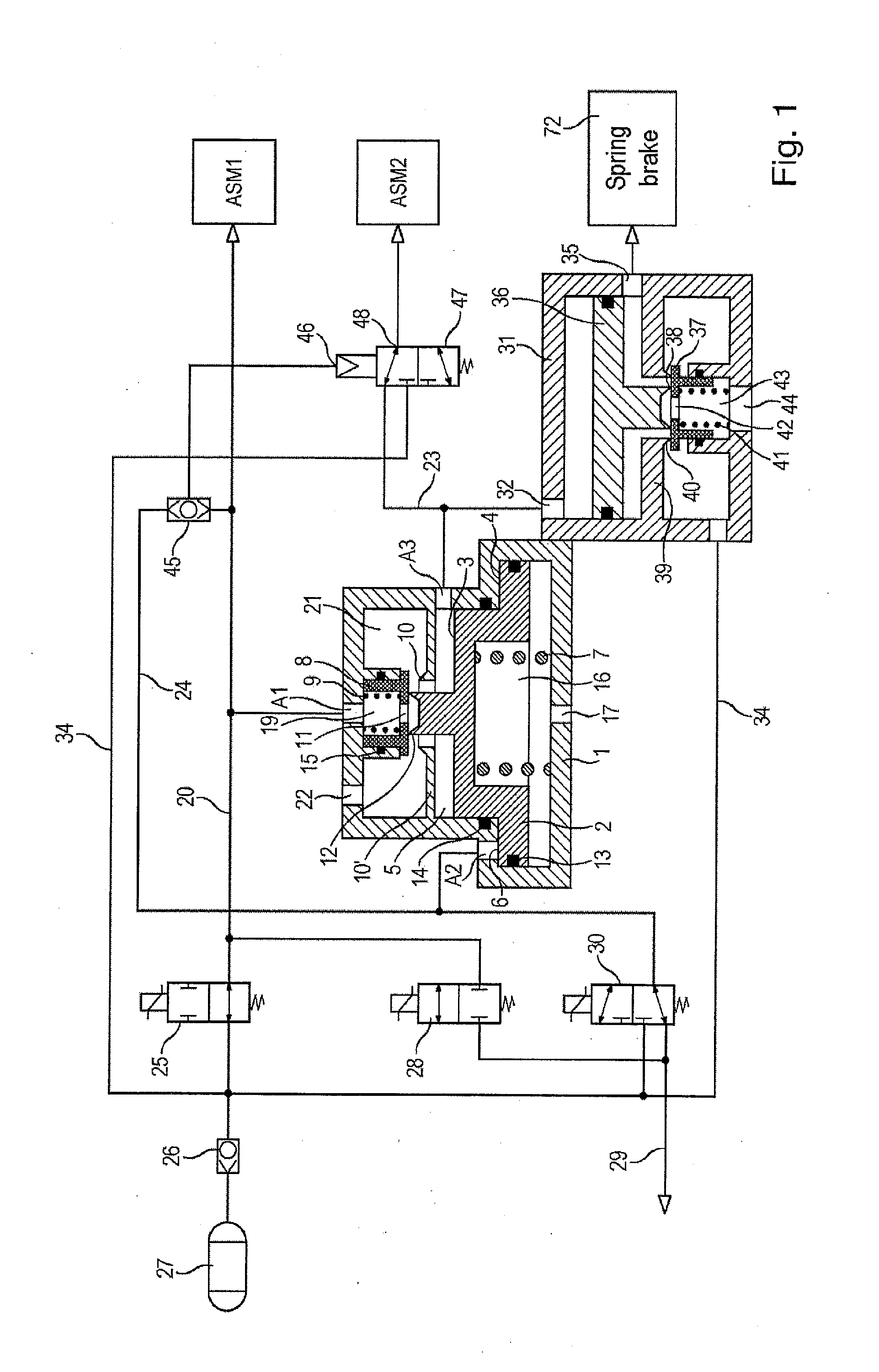
[0059]In the first illustrative embodiment in FIGS. 1 to 5, a parking brake valve 1 having a piston 2 is shown, said piston being configured as a stepped piston which has a first piston face 3 and a second piston face 4. The first piston face 3 delimits a first space 5, and the second piston face 4 delimits a second space 6. The two piston faces 3 and 4 are coaxial with one another and are each of a size sufficient to move the piston 2 against a stop counter to a spring force above a predetermined pressure, this predetermined pressure being lower than the supply pressure. The piston 2 is loaded by a spring 7, which pushes the piston 2 in a direction in which the two piston faces 3 and 4 reduce the size of the two spaces 5 and 6.

[0060]The parking brake valve 1 has a second movable piston 8, which is preloaded by a second spring 9 in the direction of the piston 2 and in the direction of a first valve seat 10. An opening 11 facing the first space 5 is provided in the bottom of the seco...


PUM


Abstract

A parking brake device having a bistable parking brake valve, a relay valve, a spring brake and electrically actuable valves, the electrically actuable valves being selectively connectable to the parking brake valve to supply pressure or atmospheric pressure, an outlet of the parking brake valve controls the relay valve, and the relay valve controls the spring brake, in which the parking brake valve has a movable piston, which is loaded by a spring and has two coaxial piston faces which delimit a first space and a second space, in which supply pressure, atmospheric pressure or a pressure which lies between them and which can be fed to the outlet of the parking brake valve can be supplied to the first space in accordance with the position of the piston, and in which the second space can be selectively connected to supply pressure or atmospheric pressure by an electrically actuable valve.

Description

FIELD OF THE INVENTION[0001]The invention relates to a parking brake device.BACKGROUND INFORMATION[0002]A parking brake device of this kind is discussed in DE 10 2008 007 877 B3. There, a spring brake cylinder is controlled by a relay valve which, for its part, is controlled by a bistable safety valve. The bistability is achieved by pneumatic feedback, with a select-low valve allowing the lower of two pressures applied to the outlet or to the inlet of the safety valve through to a control inlet of the safety valve. The safety valve is a 3 / 2-way valve having two inlets and one outlet. The first inlet can be connected selectively to a pressure medium source or atmospheric pressure by a first solenoid valve. The second inlet can likewise be connected selectively to a pressure medium source or atmospheric pressure by a second solenoid valve. The safety valve connects its outlet to one of the two inlets, depending on its operating position. The bistability of the safety valve is thus ens...

Claims


Application Information

Patent Timeline
IPC IPC(8): F16K31/02
CPCF16K31/02B60T7/20B60T13/662B60T13/683B60T15/181B60T15/182B60T17/04B60T17/221B60T13/263
Inventor HERGES, MICHAEL
Owner KNORR-BREMSE SYST FUER NUTZFAHRZEUGE GMBH
Why Eureka
Try Eureka