Robot hand and robot device

a robot and hand technology, applied in the direction of lifting devices, load-engaging elements, hoisting equipment, etc., can solve the problems of difficult to hold the object in a stable state, and the ball (inside) of the finger being in close contact with the object, and achieve the effect of low cost and simple manner

Active Publication Date: 2014-04-17
SEIKO EPSON CORP
View PDF23 Cites 30 Cited by
  • Summary
  • Abstract
  • Description
  • Claims
  • Application Information

AI Technical Summary

Benefits of technology

[0009]An advantage of some aspects of the invention is to provide a robot hand and a robot device that are capable of stabl

Problems solved by technology

However, the robot hand and the robot device in the related art have the following problems.
Thus, two finger units included in the robot hand cannot be in contact with the object at multiple contact points, which makes it difficult to hold the objec

Method used


Image

  • Robot hand and robot device
  • Robot hand and robot device
  • Robot hand and robot device

Examples


first embodiment

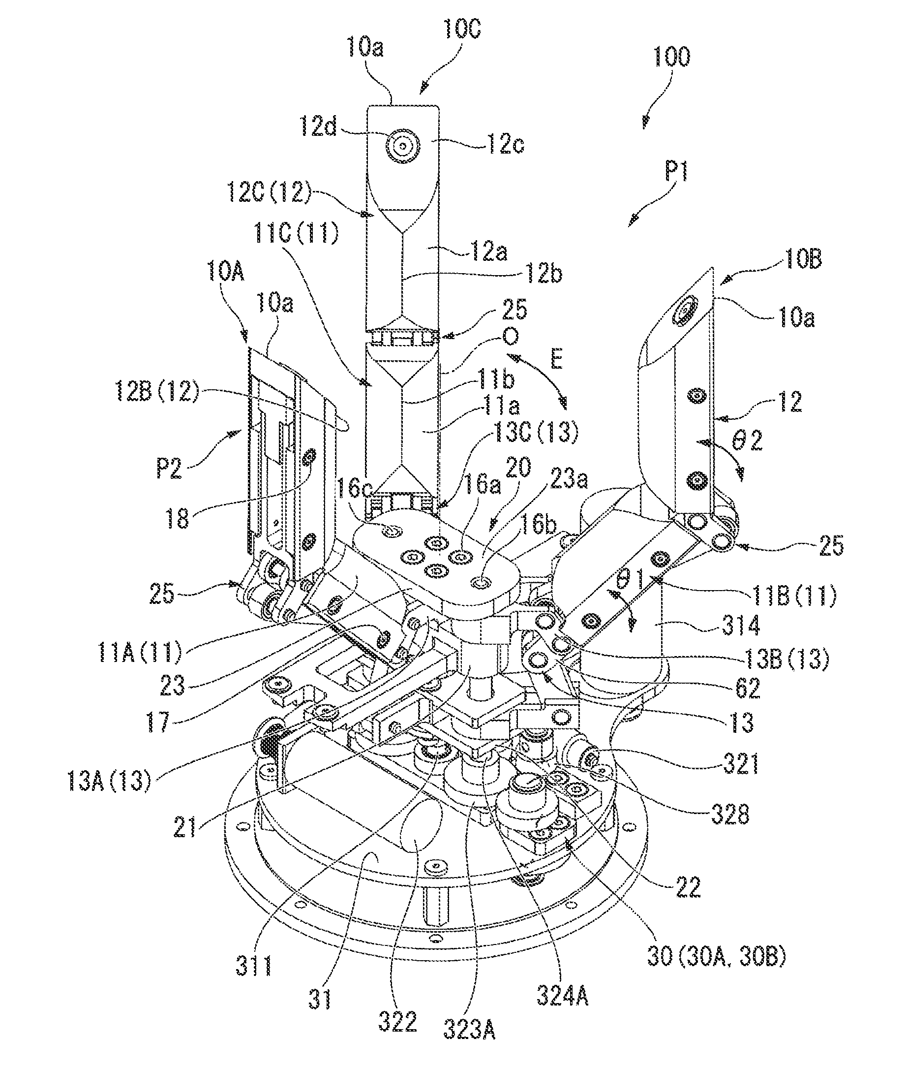
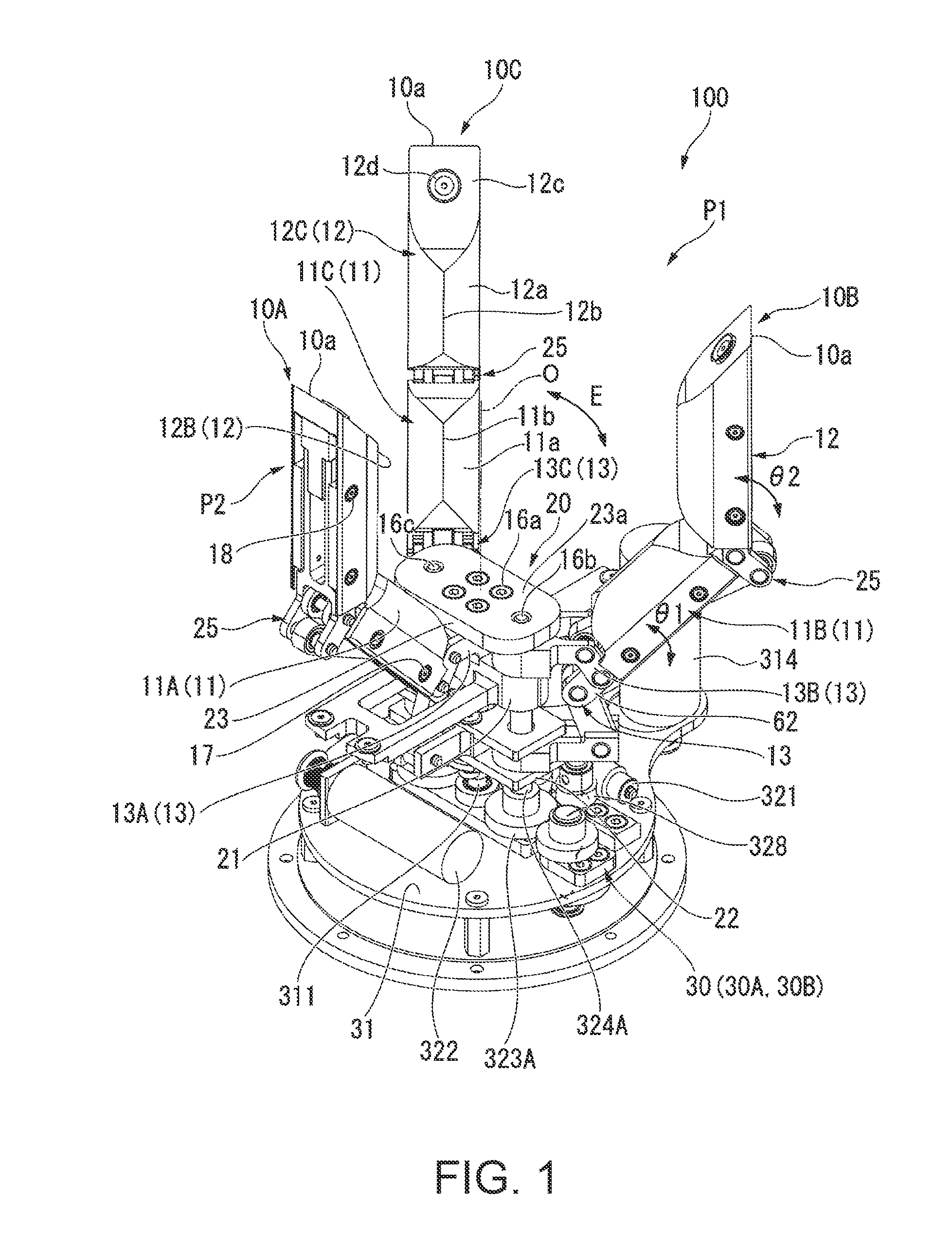
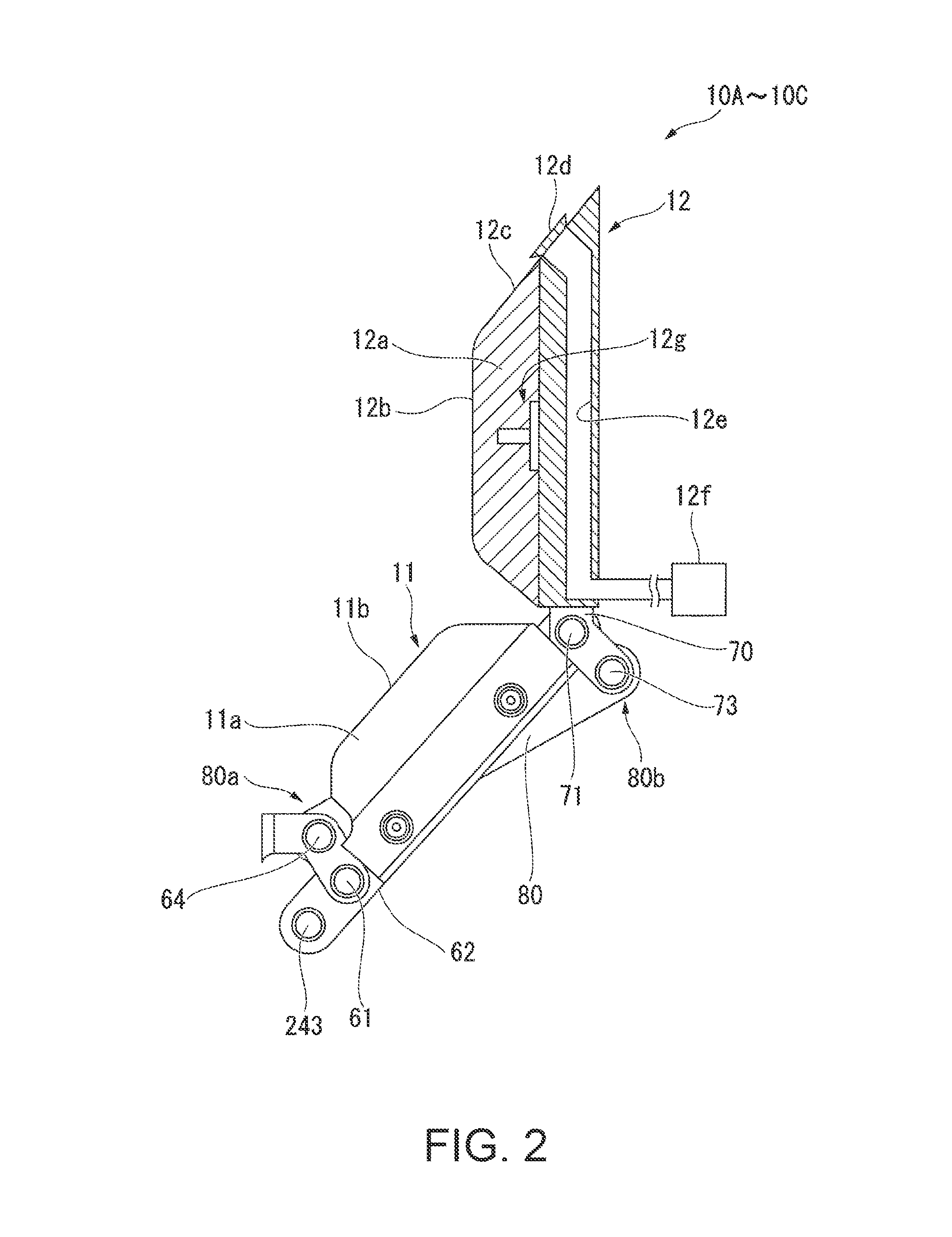
[0048]As shown in FIG. 1, a robot hand 100 according to a first embodiment is used as a holding device of an industrial robot that holds an object such as a tool or a component. The robot hand 100 may be used for other purposes (outer space field, medical field, food field, play equipment field or the like), as well as for the industrial robot.

[0049]Specifically, the robot hand 100 has a schematic configuration that includes three finger units 10A, 10B and 10C (first finger unit 10A, second finger unit 10B and third finger unit 10C), a support section (base section) 20 that supports the finger units 10A, 10B and 10C, and a drive section 30 that drives the finger units 10A, 10B and 10C.

[0050]Here, an axis that is orthogonal to a common plane (support plate to be described later) where base end portions of three finger units 10A, 10B and 10C are positioned and forms a rotation central axis line of the finger unit 10A is referred to as a hand axis (reference axis) 0. The finger units 1...

second embodiment

[0114]Hereinafter, a robot hand and a robot device according to another embodiment of the invention will be described referring to the accompanying drawings. Here, the same reference numerals are given to the same or like members and parts as in the above-described first embodiment, and description thereof will be omitted. A configuration that is different from the first embodiment will be described.

[0115]As shown in FIG. 10, a robot device 4 is used as an industrial robot arm, for example. The robot device 4 is provided to a multi-axial arm that includes amounting section 40, a first link 41, a second link 42, a third link 43, a fourth link 44, a fifth link 45 and a sixth link 46.

[0116]The mounting section 40 is mounted to a floor, a wall, a ceiling or the like, for example. The first link 41 to the sixth link 46 are serially connected in the order from the mounting section 40. Further, in the robot device 4 of the present embodiment, the mounting section 40 and the first link 41, ...

third embodiment

[0120]As shown in FIG. 11, a robot device 5 according to a third embodiment is a dual arm robot that is provided with plural (here, two) multi-axial arms (robot devices 4) according to the above-described second embodiment. In this case, the robot hand 100 is provided to each of two arms, and thus, it is possible to perform a holding operation of an object Musing the hands of two arms with the object M being interposed therebetween. In this way, it is possible to realize a holding state that is hardly achieved in the related art, and to realize various holding states.

[0121]Further, as shown in a modification example in FIG. 12, a configuration may be provided in which the robot hand 100 is provided to each of two multi-axial arms (robot devices 4) that is provided to a body section 51 of a robot device 5A. Further, if each multi-axial arm 4 is provided as a seven-axis arm having a first link 41 to a seventh link 47 and the robot hand 100 is provided to each multi-axial arm 4, it is ...


PUM


Abstract

A robot hand includes a finger unit that includes a first knuckle section that is supported to a predetermined base section and a second knuckle section that is supported to the first knuckle section; a drive section that includes a male screw that is rotatable around a predetermined screw axis by a predetermined drive source and a female screw that is screw-coupled with the male screw and moves in an axial direction of the screw axis according to rotation of the male screw, in which the female screw and the first knuckle section are connected to each other so that the first knuckle section moves in association with movement of the female screw; and a link section that connects the first knuckle section and the second knuckle section so that the second knuckle section moves in association with movement of the first knuckle section.

Description

BACKGROUND[0001]1. Technical Field[0002]The present invention relates to a robot hand and a robot device.[0003]2. Related Art[0004]In the related art, a robot hand has been proposed that is mounted at a tip of an industrial robot arm or the like and holds and releases an object to perform a predetermined operation. More specifically, a multifunctional robot hand has been proposed that holds a tool to perform an operation such as assembly of components and holds minute components to arrange the minute components with accuracy (for example, refer to JP-A-60-25686).[0005]JP-A-60-25686 discloses a robot hand technique that uses a differential gear mechanism and a spring as a passive element and can reliably and stably hold a holding target (object) in spite of change in the shape of the object, thereby having sufficient adaptability against external disturbance.[0006]However, the robot hand and the robot device in the related art have the following problems.[0007]That is, in the robot h...

Claims


Application Information

Patent Timeline
IPC IPC(8): B25J15/00B25J18/02
CPCB25J18/02B25J15/0009
Inventor NAMMOTO, TAKASHIKOSUGE, KAZUHIROYAMAGUCHI, KENGOHARA, KOSUKE
Owner SEIKO EPSON CORP
Why Eureka
Try Eureka