Radially embedded permanent magnet rotor and methods thereof

a permanent magnet and rotor technology, applied in the field of electric motors, can solve the problems of limited life of adhesives and dramatic rise in the cost of rare earth magnets, and achieve the effect of facilitating the retention of at least one permanent magn

Active Publication Date: 2014-04-17
REGAL BELOIT AMERICA
View PDF12 Cites 30 Cited by
  • Summary
  • Abstract
  • Description
  • Claims
  • Application Information

AI Technical Summary

Benefits of technology

[0005]In one embodiment, a permanent magnet rotor is provided. The permanent magnet rotor includes at least one permanent magnet and a substantially cylindrical rotor core including an outer edge and an inner edge defining a central opening. The rotor core includes a radius R, at least one pole, and at least one radial aperture extending radially though the rotor core from the outer edge to a predetermined depth less than the radius. The at least one radial aperture is configured to receive the at least one permanent magnet. The rotor further includes at least one protrusion extending into the at least one radial aperture, the at least one protrusion positioned substantially along a bottom of the at least one radial aperture and configured to facilitate retention of the at least one permanent magnet within the at least one radial aperture.
[0006]In another embodiment, an electric machine is provided. The electric machine includes a machine housing, a st

Problems solved by technology

However, adhesives have a limited life due to factors such as temperature, temperature cycling, and environmental conditions.
However, the cost of rare earth magnets has drastically ris

Method used


Image

  • Radially embedded permanent magnet rotor and methods thereof
  • Radially embedded permanent magnet rotor and methods thereof
  • Radially embedded permanent magnet rotor and methods thereof

Examples


Embodiment Construction

[0030]Due to increased costs of rare earth magnets and copper used for windings, lower cost alternative materials are desirable in the design and manufacture of electric motors. This disclosure provides designs and methods using material alternatives to rare earth magnets and copper windings while reducing or recapturing the efficiency losses associated with those alternative materials and reducing or eliminating an increase of the length of the motor.

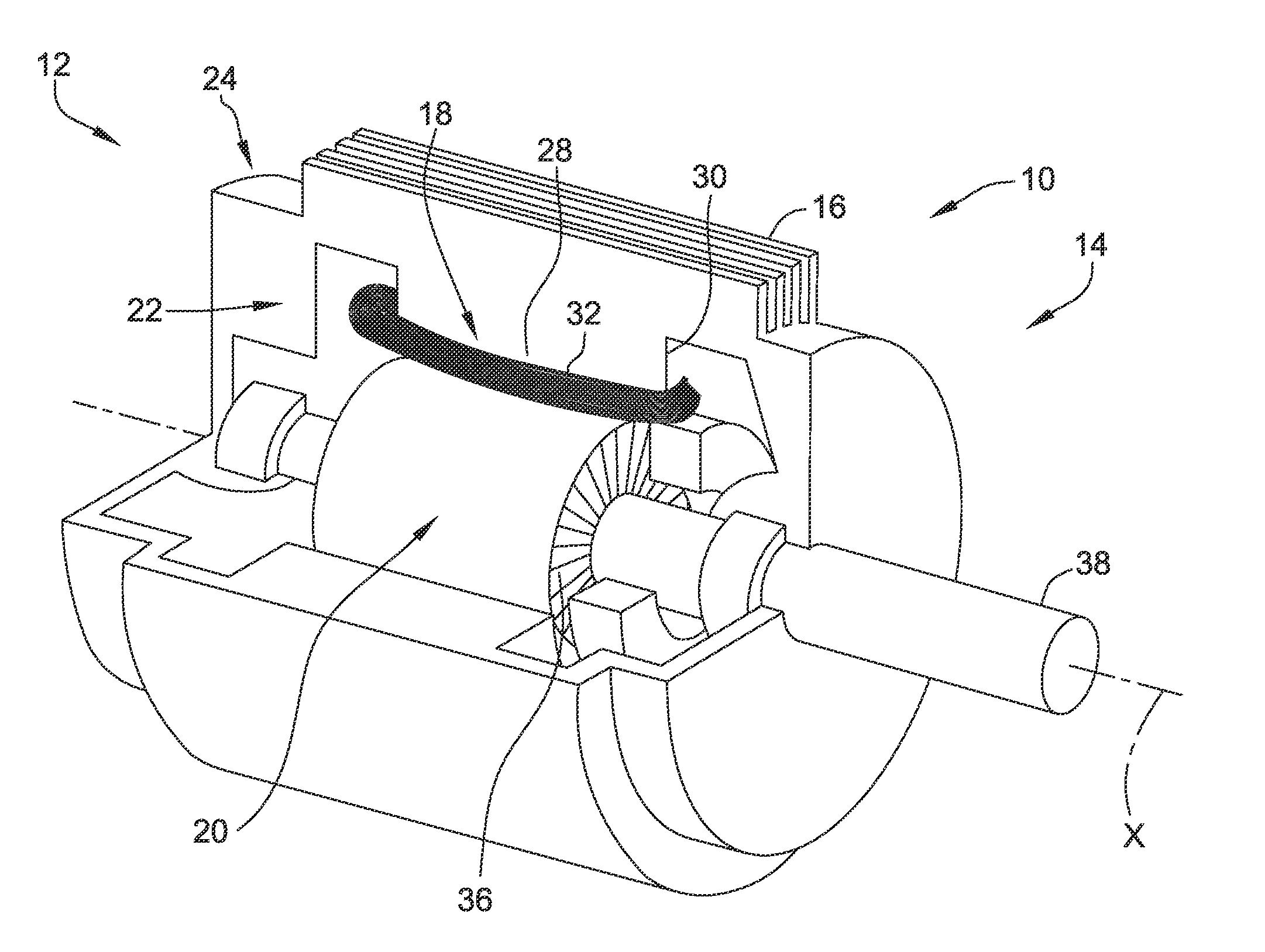
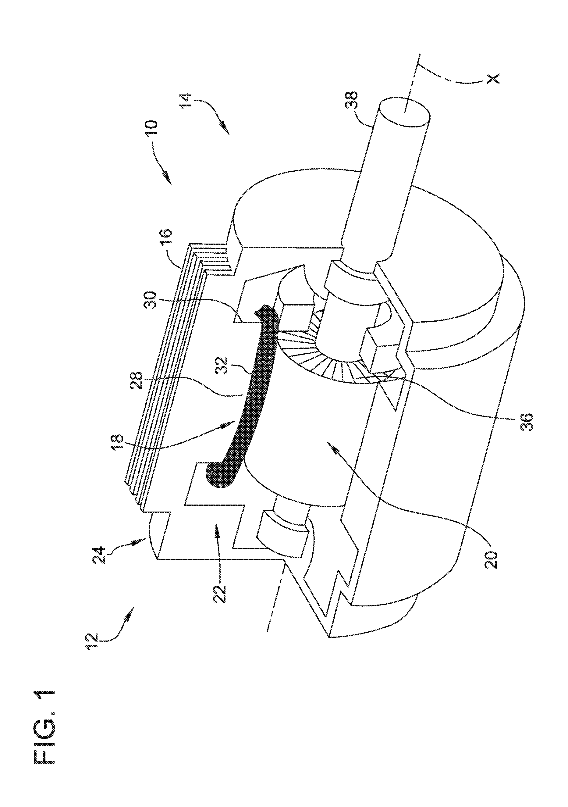
[0031]FIG. 1 is a perspective cut-away view of an exemplary electric motor 10. Although referred to herein as electric motor 10, electric motor 10 can be operated as either a generator or a motor. Electric motor 10 includes a first end 12, a second end 14, and a motor assembly housing 16. Electric motor 10 also includes a stationary assembly 18 and a rotatable assembly 20. Motor assembly housing 16 defines an interior 22 and an exterior 24 of motor 10 and is configured to at least partially enclose and protect stationary assembly 18 an...


PUM

PropertyMeasurementUnit
Radiusaaaaaaaaaa
Depthaaaaaaaaaa
Efficiencyaaaaaaaaaa

Abstract

In one embodiment, a permanent magnet rotor is provided. The permanent magnet rotor includes at least one permanent magnet and a substantially cylindrical rotor core including an outer edge and an inner edge defining a central opening. The rotor core includes a radius R, at least one pole, and at least one radial aperture extending radially though the rotor core from the outer edge to a predetermined depth less than the radius. The at least one radial aperture is configured to receive the at least one permanent magnet. The rotor further includes at least one protrusion extending into the at least one radial aperture, the at least one protrusion positioned substantially along a bottom of the at least one radial aperture and configured to facilitate retention of the at least one permanent magnet within the at least one radial aperture.

Description

BACKGROUND[0001]The field of the disclosure relates generally to electric motors, and more particularly, to radially embedded permanent magnet rotors and alternative materials for use in electric motors.[0002]Various types of electric machines include permanent magnets. For example, a brushless direct current (BLDC) motor may include a plurality of permanent magnets coupled to an exterior surface of a rotor core. Typically, the permanent magnets are coupled to the exterior surface of the rotor core using an adhesive and / or an outer retaining covering. This coupling between the permanent magnets and the rotor core must resist forces exerted on the permanent magnets during high speed rotation tending to separate the permanent magnets from the motor.[0003]Permanent magnets may also be positioned within a rotor core, commonly referred to as an interior permanent magnet rotor. Slots are formed within the rotor, and magnets are inserted into the slots. The magnet slots must be larger than...

Claims


Application Information

Patent Timeline
IPC IPC(8): H02K1/27H02K15/03
CPCH02K15/03H02K1/2773H02K21/16H02K2201/03H02K2213/03Y10T29/49012H02K3/02
Inventor BRAHMAVAR, SUBHASH MARUTIRAOMANZ, LESTER BENJAMINCHRETIEN, LUDOVIC ANDRERASHIDZADEH, CHANGIZIONEL, DAN MIRCEA
Owner REGAL BELOIT AMERICA
Why Eureka
Try Eureka