
Transparent antennas on a display device

a display device and transparent technology, applied in the field of antennas, can solve the problems of increasing protocols, increasing data rate and operation over multiple bands,

Inactive Publication Date: 2014-04-17
SNAPTRACK
View PDF8 Cites 161 Cited by
  • Summary
  • Abstract
  • Description
  • Claims
  • Application Information

AI Technical Summary

Benefits of technology

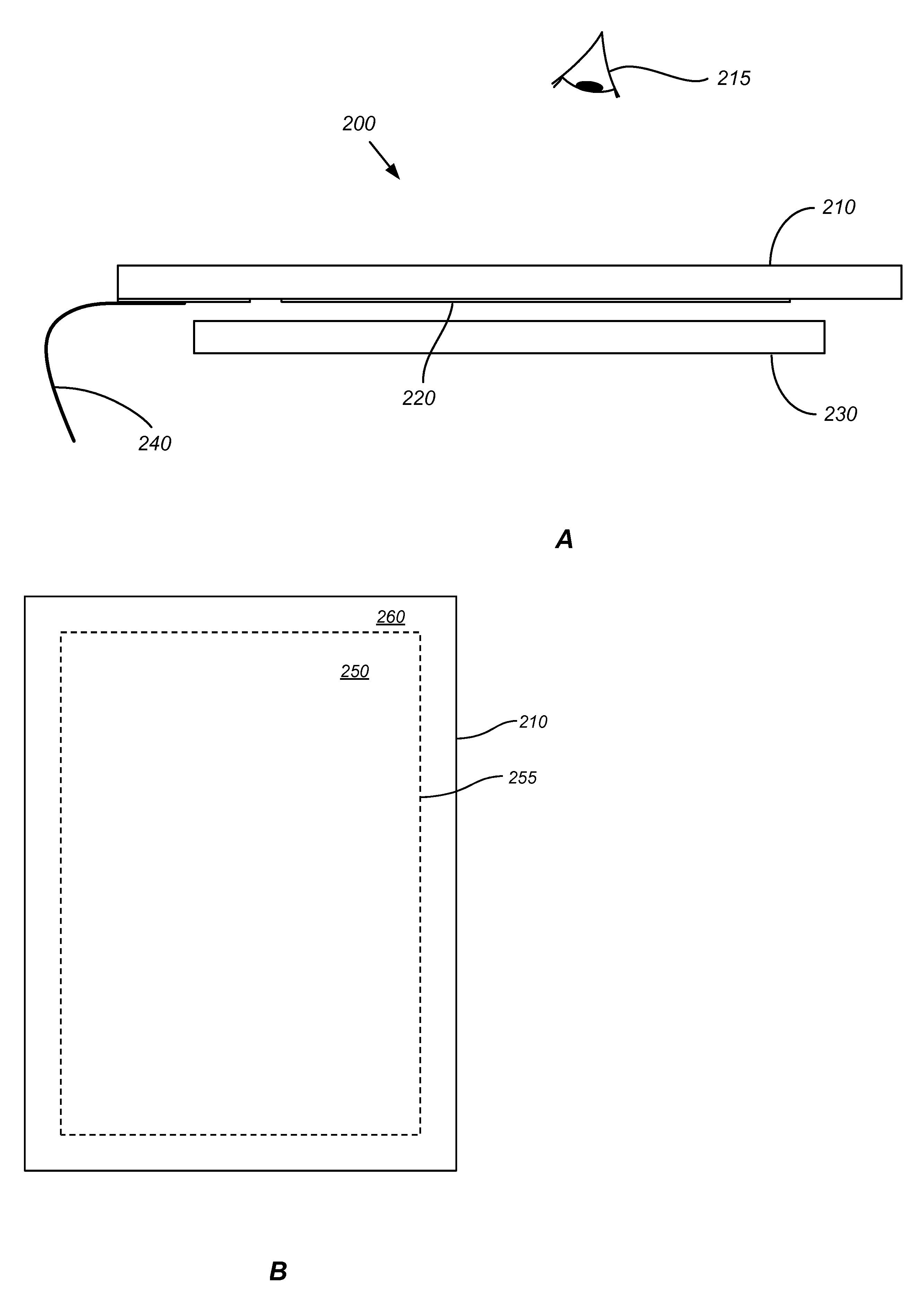
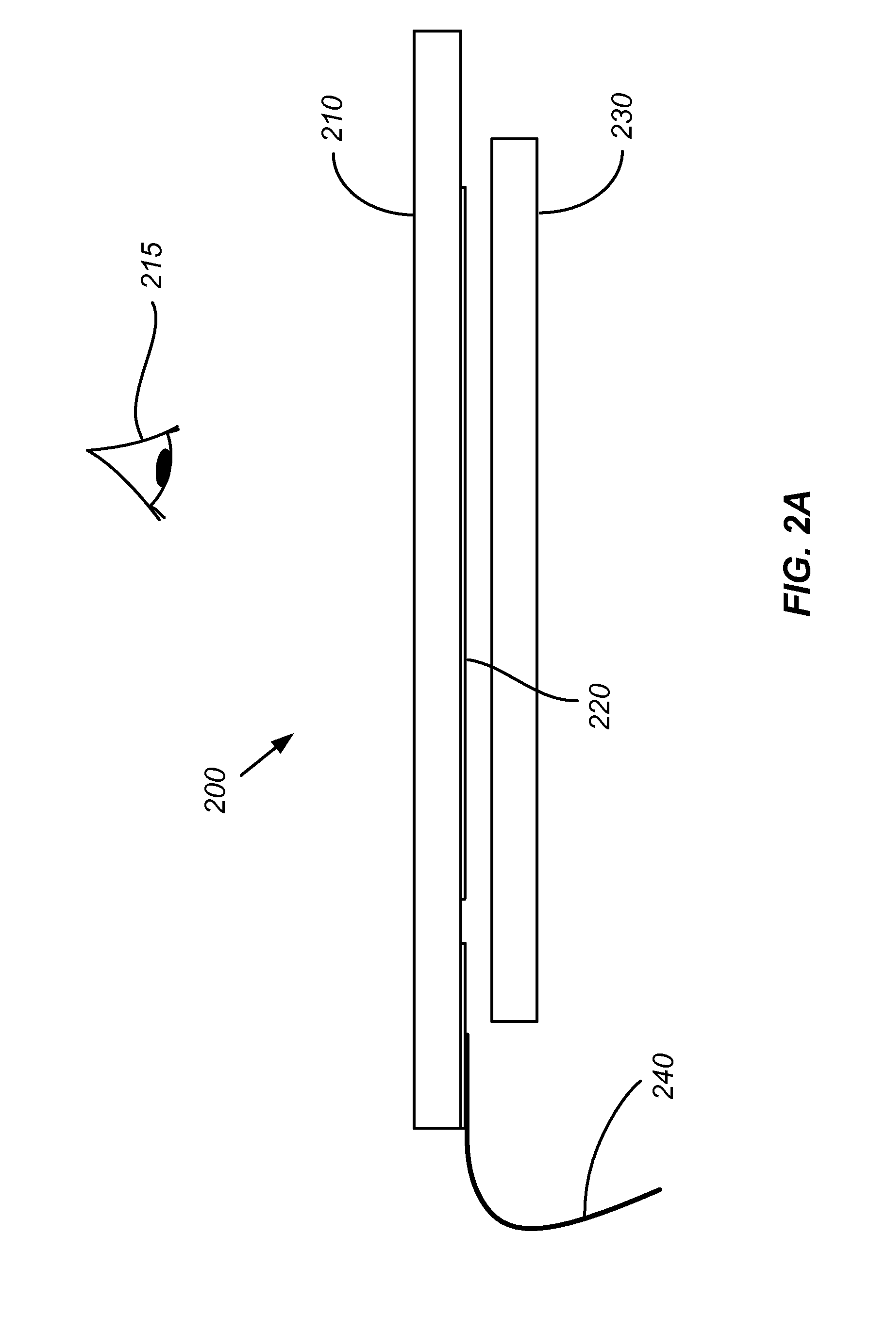
The patent describes several innovative aspects related to a display device. Firstly, the device includes a transparent substrate with a display region and a non-display region, where a first antenna is formed in the display region and a second antenna is cooperatively coupled with the first antenna. The second antenna can be substantially non-transparent. Secondly, the device includes means for displaying an image and means for receiving a wireless signal, which can be a printed circuit board in electrical communication with the first antenna. The receiving means is substantially transparent. Thirdly, the device includes a method of manufacturing a display device by providing a transparent substrate with a display region and a non-display region, where a first antenna is formed in the display region and a second antenna is cooperatively coupled with the first antenna. The second antenna can be substantially non-transparent. Fourthly, the device includes a method of detecting a user's head and switching from a display-side antenna to an enclosure antenna when the user's head is proximate the display-side antenna. Fifthly, the device includes a machine-readable, non-transitory storage medium containing computer executable instructions for operating a display device by detecting a user's head and switching from a display-side antenna to an enclosure antenna when the user's head is proximate the display-side antenna. These innovative aspects enhance the performance and user experience of the display device.

Problems solved by technology

Many mobile display devices such as cellular phones, smart phones, e-readers, and tablet computers have increasingly limited space to place antennas for wireless communications, while demands for higher data rates and operation over multiple bands and protocols have increased.

Method used


Image

  • Transparent antennas on a display device
  • Transparent antennas on a display device
  • Transparent antennas on a display device

Examples


Embodiment Construction

[0042]The following description is directed to certain implementations for the purposes of describing the innovative aspects of this disclosure. However, a person having ordinary skill in the art will readily recognize that the teachings herein can be applied in a multitude of different ways. The described implementations may be implemented in any device, apparatus, or system that can be configured to display an image, whether in motion (such as video) or stationary (such as still images), and whether textual, graphical or pictorial. More particularly, it is contemplated that the described implementations may be included in or associated with a variety of electronic devices such as, but not limited to: mobile telephones, multimedia Internet enabled cellular telephones, mobile television receivers, wireless devices, smartphones, Bluetooth® devices, personal data assistants (PDAs), wireless electronic mail receivers, hand-held or portable computers, netbooks, notebooks, smartbooks, ta...


PUM

PropertyMeasurementUnit
sizesaaaaaaaaaa
frequenciesaaaaaaaaaa

Abstract

This disclosure provides systems, methods and apparatus for a display device with at least one transparent antenna. In one aspect, a transparent antenna is formed on the surface of a transparent substrate and is cooperatively coupled with a second antenna. The transparent antenna can avoid substantial interference with images produced by the display device.

Description

TECHNICAL FIELD[0001]This disclosure relates generally to antennas and more particularly to transparent antennas on a display device, such as an electromechanical systems (EMS) display device.DESCRIPTION OF THE RELATED TECHNOLOGY[0002]Electromechanical systems (EMS) include devices having electrical and mechanical elements, actuators, transducers, sensors, optical components such as mirrors and optical films, and electronics. EMS devices or elements can be manufactured at a variety of scales including, but not limited to, microscales and nanoscales. For example, microelectromechanical systems (MEMS) devices can include structures having sizes ranging from about a micron to hundreds of microns or more. Nanoelectromechanical systems (NEMS) devices can include structures having sizes smaller than a micron including, for example, sizes smaller than several hundred nanometers. Electromechanical elements may be created using deposition, etching, lithography, and / or other micromachining pr...

Claims


Application Information

Patent Timeline
Patent Type & Authority Applications(United States)
IPC IPC(8): H01Q1/24H01P11/00H04B1/44G06F15/00G06F3/01
CPCH01Q1/243H01Q21/28G06F1/1698Y10T29/49018
Inventor BURNS, DAVID WILLIAMGRIFFITHS, JONATHAN CHARLES
Owner SNAPTRACK
Learn More