In-Flight Attitude Control and Direct Thrust Flight Control System of a Vehicle and Craft Comprising Such a System

a technology of flight control system and thrust control, which is applied in the direction of cosmonautic vehicles, rocket engine plants, machines/engines, etc., can solve the problems of increased complexity of the control and maintenance of the thrust control system, increased operating cost, and reduced thrust control accuracy, so as to improve steering accuracy and response time very short

Active Publication Date: 2014-04-24
ARIANEGRP SAS
View PDF5 Cites 7 Cited by
  • Summary
  • Abstract
  • Description
  • Claims
  • Application Information

AI Technical Summary

Benefits of technology

[0018]Compared with the above-described DACSs, the system of the invention with two sets of four valves arranged as specified is advantageous in that with a small number of valves it enables all desired trajectory and attitude corrections to be performed instantaneously or almost instantaneously, and thus with a response time that is very short.
[0019]Various corrections, in particular trajectory diversion, are obtained by selectively causing one or more valves in each set of valves to open simultaneously, and that also gives rise to other advantages.
[0020]Firstly, by sharing the required thrusts over the two sets of valves, it becomes possible for a given desired resultant thrust to reduce the individual thrust requested of each valve. For a given level of performance in terms of corrective thrust, the weight and the dimensions of the valves, and the power required for activating them, can be smaller, and / or the pressure in the thruster body can be decreased, thereby in either case improving steering accuracy.
[0021]Furthermore, sharing valve resources for the functions of side-force steering and of attitude control advantageously enables identical valves to be used, thereby contributing to simplifying the definition and the provision of the system and thus reducing development and fabrication costs.
[0022]A preferred configuration for the valves at the outside of the thruster body also contributes to simplifying the definition and the provision of the system, while also presenting good safety from a pyrotechnic point of view.
[0023]In addition, when generating gas by means of a solid propellant, using a single block of propellant also goes towards simplification and towards a reduction in costs.

Problems solved by technology

In addition, the location of the divert valves within the thruster body and between two blocks of propellant is not optimal in terms of pyrotechnic safety, in particular during assembly operations, and it makes control and maintenance of the propulsive system more complex.
Furthermore, the location of the divert valves limits operation duration because they are exposed to very high temperatures, or else puts a limit on gas temperature, and in either case performance suffers.
This leads to a loss in response time and in maneuverability, and also to significant excess consumption.
Roll control is therefore not possible.

Method used


Image

  • In-Flight Attitude Control and Direct Thrust Flight Control System of a Vehicle and Craft Comprising Such a System
  • In-Flight Attitude Control and Direct Thrust Flight Control System of a Vehicle and Craft Comprising Such a System
  • In-Flight Attitude Control and Direct Thrust Flight Control System of a Vehicle and Craft Comprising Such a System

Examples


example 1

Trajectory Diversion

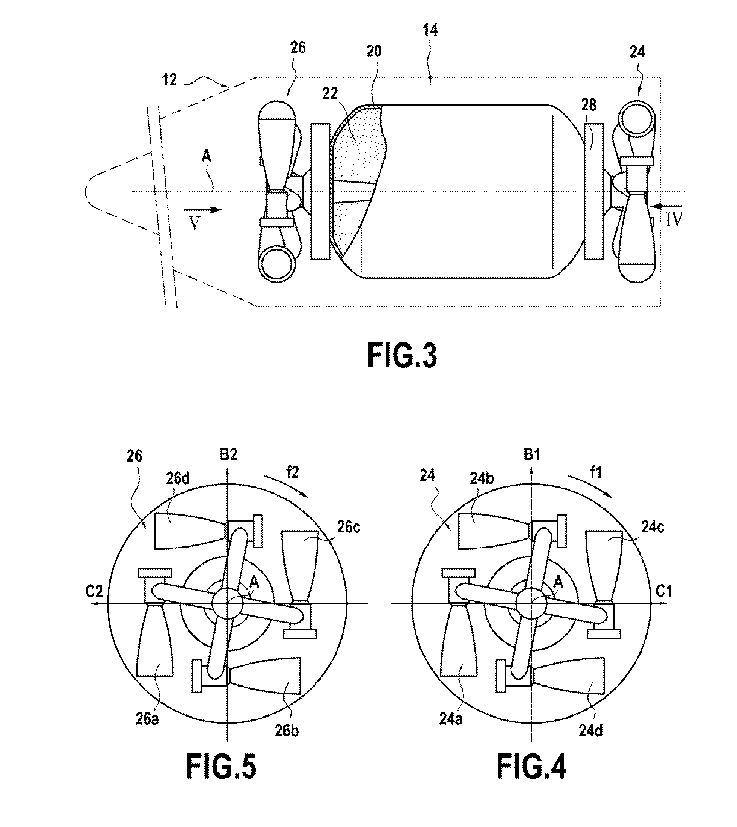
[0051]A trajectory correction may be required for example in which the trajectory is diverted by applying side thrust F as shown in FIG. 6, this thrust being resolved into a component F1 along an axis B parallel the axes B1 and B2, and a component F2 along an axis C parallel to the axes C1 and C2.

[0052]FIG. 7 is a very diagrammatic view showing the valves that remain open under the control of the control device 28, the other valves being closed. The component F1 is produced by the valves 24a and 26a with their openings being adjusted so that each of them generates a thrust F1 / 2. The component F2 is produced by the valves 24b and 26b with their openings being adjusted so that each of them generates a thrust F2 / 2. The other valves of the sets 24 and 26 are closed.

[0053]The valves 24a and 26a are situated on two opposite sides of the axis A, such that the torques produced by the thrusts from those two valves cancel. The same applies for the valves 24b and 26b. Thus,...

example 2

Correcting Roll

[0054]A roll correction is produced in this example by simultaneously opening two valves that generate thrusts in opposite directions in one of the sets of valves, depending on the direction of the rotation to be corrected.

[0055]FIG. 8 shows only the valves 26a and 26c in the set 26 at the front of the thruster body being opened in order to perform a roll correction that is applied in the direction of rotation f2. The valves of the set 24 at the front of the thruster may be closed or they may be kept at a common degree of opening that is small enough to avoid canceling the effect of the valves 26a and 26c. The valves 26a and 26c generate thrust of the same amplitude in order to avoid inducing any resultant side thrust.

[0056]In a variant, all four valves of the set 26 could be open.

[0057]Naturally, a roll correction for application in the direction of rotation f1 could be produced by thrust from two or four valves of the set 24.

example 3

Yaw Correction

[0058]A yaw movement is used herein to mean oscillation about an axis parallel to the axes B1 and B2.

[0059]Yaw correction must be obtained by generating side thrust F3 perpendicular to the axis B1 and B2 using one valve in each of the sets 24 and 26.

[0060]In the example of FIG. 9, the yaw correction is obtained by opening the valve 26d that exerts a thrust F3, and the valve 24b that likewise exerts a thrust F3, the other valves being closed. In principle no roll is generated, but if necessary, compensation for any roll may be provided as described above.


PUM


Abstract

A system for in-flight attitude control and side-force steering includes a thruster body and a plurality of valves capable of generating side thrusts put into communication with the thruster body. The valves are arranged in two sets of valves spaced apart from each other towards the front and towards the rear of the thruster body in substantially symmetrical manner relative to the center of gravity of the vehicle situated on a longitudinal axis (A) of the vehicle. Each set comprises a first pair of valves generating thrust in opposite directions along axes that are not in alignment and are parallel to a first axis, and a second pair of valves generating thrust in opposite directions along axes that are not aligned and are parallel to a second axis. The first and second axes are distinct and perpendicular to the longitudinal axis of the vehicle.

Description

BACKGROUND OF THE INVENTION[0001]The invention relates to a system for providing a vehicle with in-flight attitude control and side-force steering, also known as a divert and attitude control system (DACS).[0002]The invention is particularly applicable to the high or terminal portions of interceptor missiles used for defense against ballistic missiles, and specifically to maintaining a desired trajectory and attitude at the end of a mission. Nevertheless, the invention can be used for other types of air or space vehicle, e.g. for anti-aircraft defense missiles, air-to-air missiles, atmospheric reentry vehicles, or indeed space exploration modules.[0003]A known DACS for a vehicle constituting the terminal portion of an interceptor missile is shown very diagrammatically in FIG. 1. This DACS 1 comprises a thruster body 2 having two propellant blocks 3 ideally arranged on either side of a metal ring 4 carrying side-force steering or trajectory divert valves 5. Four divert valves 5 are p...

Claims


Application Information

Patent Timeline
Patent Type & Authority Applications(United States)
IPC IPC(8): F02K9/08
CPCF02K9/08B64G1/26F42B10/663B64G1/401F42B10/66
Inventor CAUBET, PASCALFERRANT, AURORE
Owner ARIANEGRP SAS
Why Eureka
Try Eureka