Drainage structure for corrugated-fin heat exchanger
- Summary
- Abstract
- Description
- Claims
- Application Information
AI Technical Summary
Benefits of technology
Problems solved by technology
Method used
Image
Examples
Embodiment Construction
[0024]Now, referring to the accompanying drawings, detailed description is given of embodiments of the present invention.
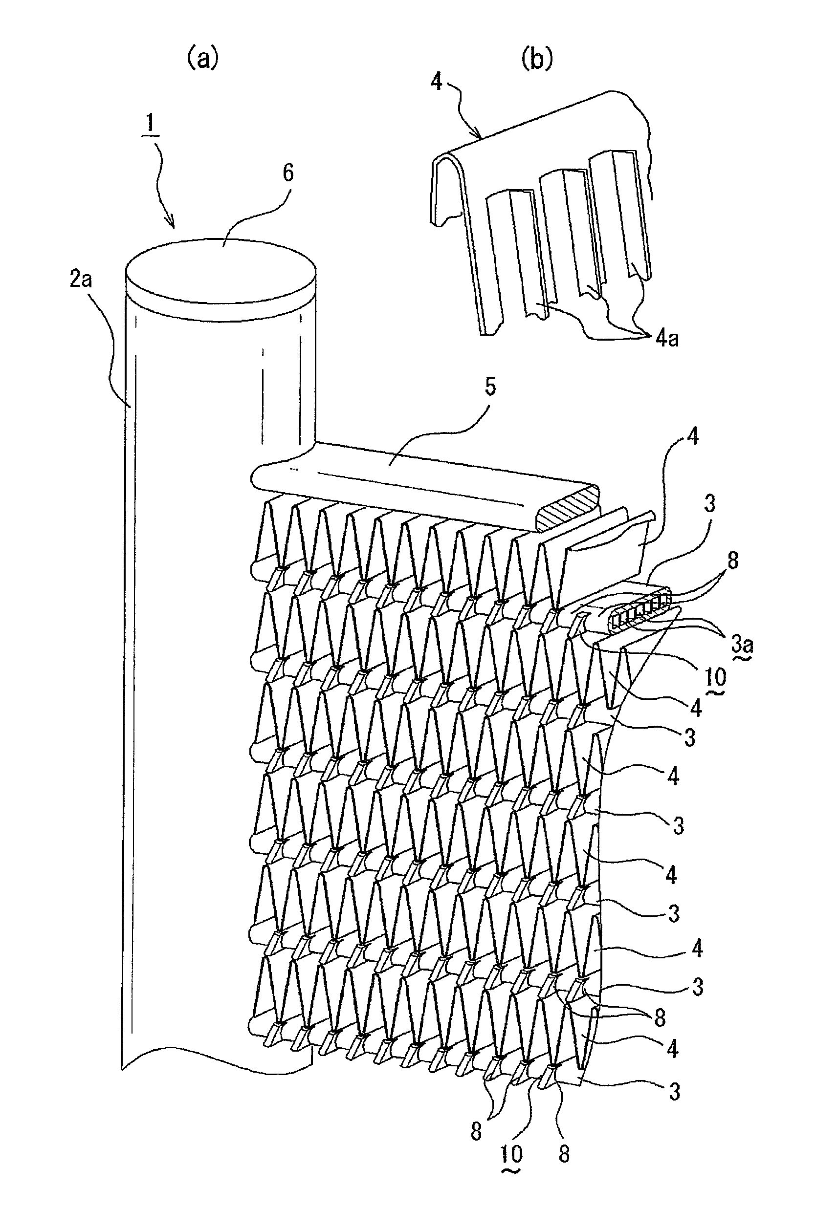
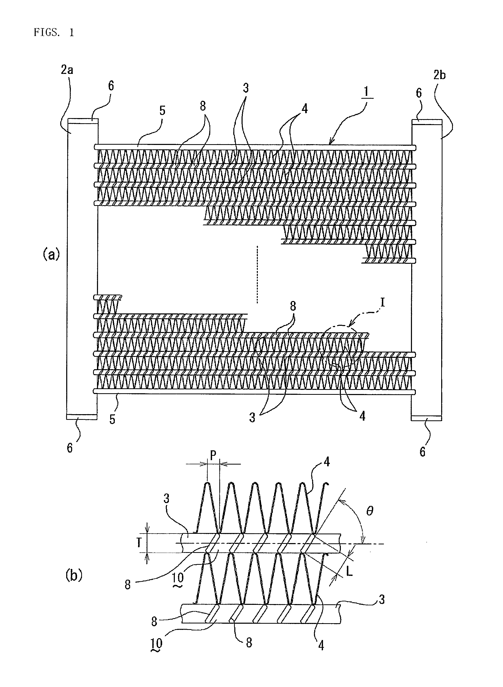
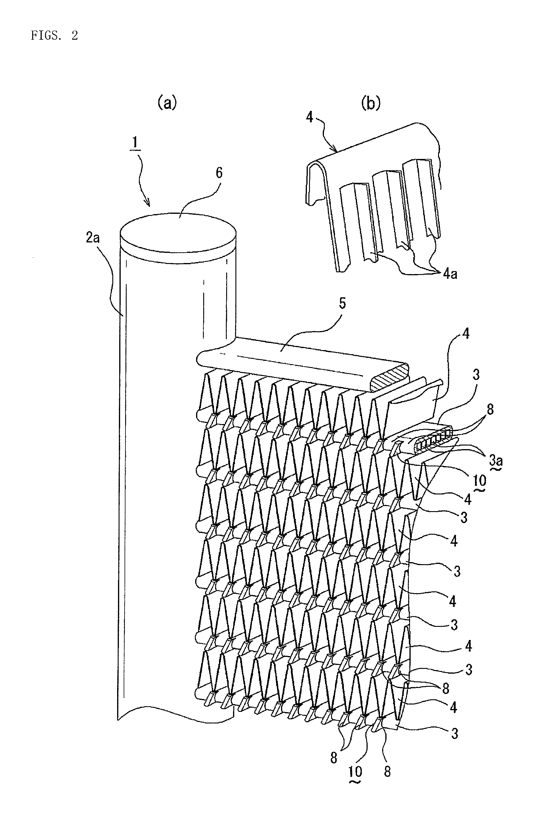
[0025]As illustrated in FIG. 1, a corrugated-fin heat exchanger 1 according to the present invention includes a pair of laterally opposing header pipes 2a and 2b each made of aluminum (including aluminum alloy), a plurality of flat heat exchange tubes 3 bridged (continuously provided) in parallel to one another in a horizontal direction between the header pipes 2a and 2b, and corrugated fins 4 each interposed between adjacent heat exchange tubes 3, the heat exchange tubes 3 and the corrugated fins 4 being brazed to the header pipes 2a and 2b.
[0026]In this case, the heat exchange tube 3 has a plurality of sectioned heating medium passages 3a formed therein. Further, on the upper outside and the lower opening side of the corrugated fins 4 at the upper and lower ends, side plates 5 made of aluminum are brazed, respectively. Further, at the upper and lower opening en...
PUM
 Abstract
Description
Claims
Application Information
 - R&D
- Intellectual Property
- Life Sciences
- Materials
- Tech Scout
- Unparalleled Data Quality
- Higher Quality Content
- 60% Fewer Hallucinations
Browse by: Latest US Patents, China's latest patents, Technical Efficacy Thesaurus, Application Domain, Technology Topic, Popular Technical Reports.
© 2025 PatSnap. All rights reserved.Legal|Privacy policy|Modern Slavery Act Transparency Statement|Sitemap|About US| Contact US: help@patsnap.com


