Method and device for charging coal-containing material and iron carrier material

a technology of iron carrier material and charging bin, which is applied in the direction of charge manipulation, furnace monitoring device, furnace, etc., can solve the problems of carbonaceous material and iron carrier material being added separately into the melter gasifier, affecting the operation of the plant, and affecting the operation of the charging bin. , to achieve the effect of reducing the cost of the separate addition

Active Publication Date: 2014-04-24
POHANG IRON & STEEL CO LTD +1
View PDF2 Cites 3 Cited by
  • Summary
  • Abstract
  • Description
  • Claims
  • Application Information

AI Technical Summary

Benefits of technology

[0014]Using such a method, the melter gasifier requires fewer plant parts and openings for charging than when lumped carbonaceous material and iron carrier material enter the melter gasifier separately.
[0015]Hot iron carrier material is understood to mean iron carrier material having a temperature higher than 100° C., e.g., higher than 200° C., such as higher than 300° C. The iron carrier material contains elementary iron and/or iron oxide. The iron carrier material is present in lump form, in lump form with a proportion of fines, or as fine grain (such as less than 10 mm).
[0016]The carbonaceous material is present in lump form. The proportion of coal in the lumped carbonaceous material represents at least 50% by weight, e.g., at least 70% by weight, such as 90% by weight. In this case the proportion by weight relates to the weight of the constituents of the lumped carbonaceous material at the time when the constituents are loaded into the charging bin. In addition to coal, the lumped carbonaceous material may also contain coke, for example.
[0017]No further details of the fluxes such as limestone and/or dolomite and/or quartz, for example, which are also char...

Problems solved by technology

Pyrolysis of coal or carbonaceous briquettes at high temperatures results in the development and release of volatile hydrocarbons and tar.
Therefore the carbonaceous material cannot be stored together with hot iron carrier material in a charging bin, since the development and release of volatile hydrocarbons and tar, triggered by the contact with the hot iron carrier material, would result in conglutination and blockages in the charging bin and in the lines transporting the material to the melter gasifier.
The separate addition of carbonaceous material and iron carrier material into the melter gasifier involves considerable expense in terms of the construction and maintenance of those plant parts required for the separate addition.
Moreover, in the case of separate ad...

Method used


Image

  • Method and device for charging coal-containing material and iron carrier material
  • Method and device for charging coal-containing material and iron carrier material
  • Method and device for charging coal-containing material and iron carrier material

Examples


Embodiment Construction

[0054]Reference will now be made in detail to the preferred embodiments, examples of which are illustrated in the accompanying drawings, wherein like reference numerals refer to like elements throughout.

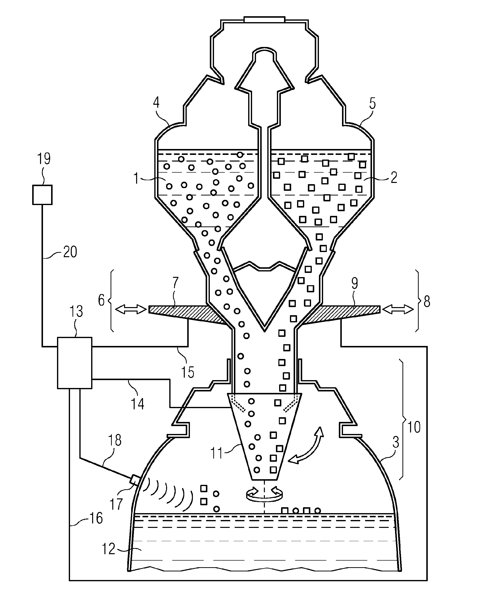
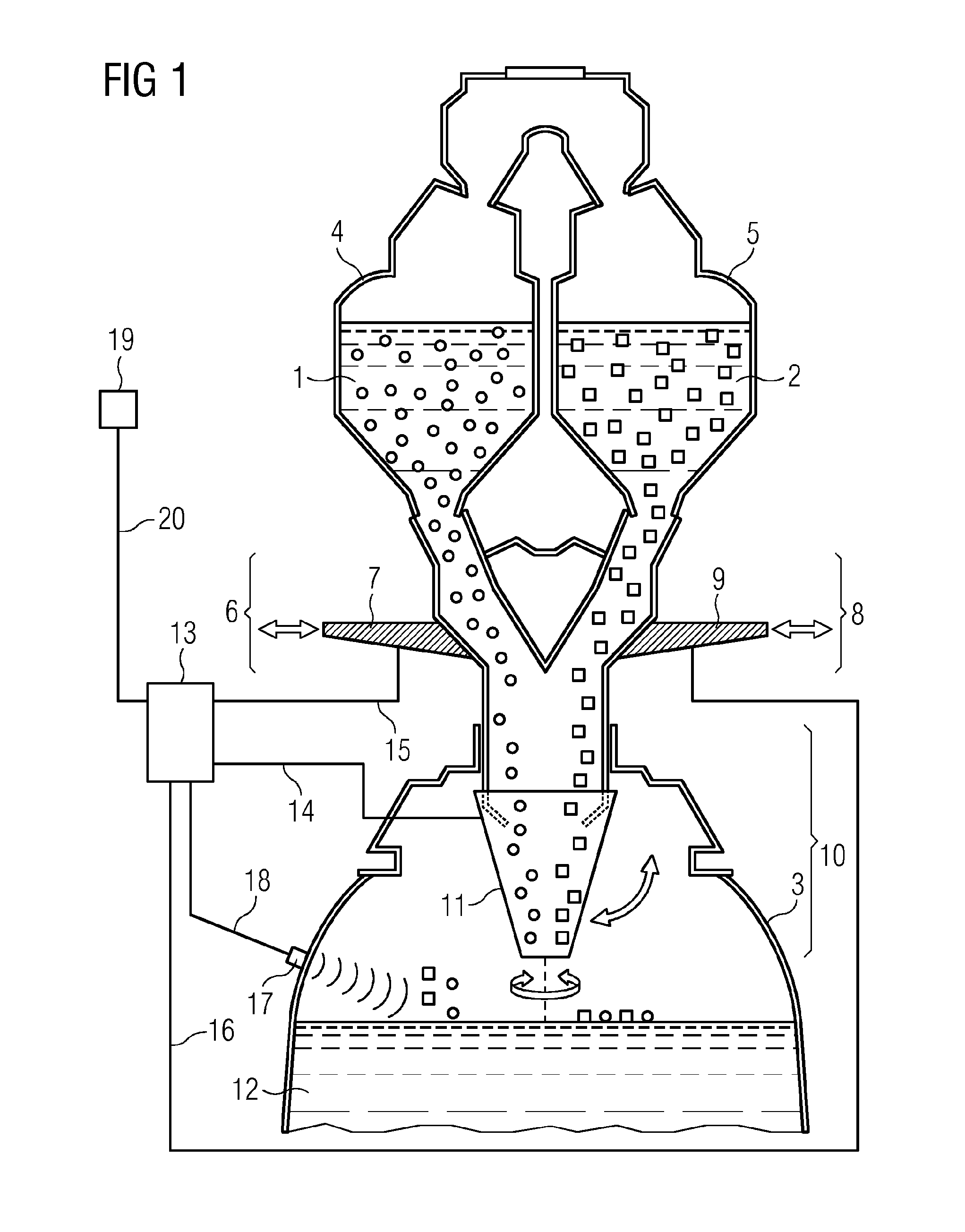
[0055]FIG. 1 shows a device for charging material, including lumped carbonaceous material 1, this being represented by circles, and hot iron carrier material 2, this being represented by squares, into a melter gasifier 3 of a smelting reduction plant. The device has a charging bin 4 for lumped carbonaceous material and a charging bin 5 for hot iron carrier material. A first discharge line 6 for lumped carbonaceous material emerges from the charging bin 4 for lumped carbonaceous material, the first discharge line including a first conveyor device 7 for regulating the discharge of lumped carbonaceous material 1. A second discharge line 8 for hot iron carrier material emerges from the charging bin 5 for hot iron carrier material, the second discharge line including a second conveyor dev...


PUM

PropertyMeasurementUnit
Grain sizeaaaaaaaaaa
Temperatureaaaaaaaaaa
Sizeaaaaaaaaaa

Abstract

A melter gasifier of a smelting reduction installation is charged by bringing together coal-containing material in lump form and iron carrier material (which may be hot) before and/or while they enter the melter gasifier. The ratio of the combined amounts of iron carrier material and coal-containing material in lump form is variable. The combined amounts of iron carrier material and coal-containing material in lump form are distributed over the cross section of the melter gasifier by a dynamic distributing device, and the ratio of the combined amounts of the iron carrier material and coal-containing material in lump form is set depending on the position of the dynamic distributing device.

Description

CROSS REFERENCE TO RELATED APPLICATIONS[0001]This application is the U.S. national stage of International Application No. PCT / EP2012 / 058499, filed, May 9, 2012 and claims the benefit thereof. The International Application claims the benefits of Austrian Application No. A723 / 2011 filed on May 19, 2011, both applications are incorporated by reference herein in their entirety.BACKGROUND[0002]1. Technical Field[0003]Described below is a method for charging material, including lumped carbonaceous (coal-containing) material and (e.g., hot) iron carrier material, into a melter gasifier of a smelting reduction plant.[0004]2. Related Art[0005]In the context of smelting reduction processes for producing pig iron in a melter gasifier, e.g. COREX® or FINEX®, material including carbonaceous material, iron carrier material and fluxes is charged into the melter gasifier. The carbonaceous material is gasified with oxygen to produce a reduction gas, the heat required to melt the iron carrier materia...

Claims


Application Information

Patent Timeline
IPC IPC(8): F27D3/00
CPCF27D3/0026F27D3/0025C21B13/002C21B13/0066C21B13/143F27D3/08F27D19/00F27D21/0035C21B13/00C21B13/14F27D21/00
Inventor AICHINGER, GEORGBERNER, FRANZEDER, THOMASMILLNER, ROBERTPLAUL, JAN-FRIEDEMANNREIN, NORBERTSCHERNEY, ANDREASWIEDER, KURTWURM, JOHANN
Owner POHANG IRON & STEEL CO LTD
Why Eureka
Try Eureka