
Apparatus and method for calibrating depth image based on relationship between depth sensor and color camera

a depth sensor and color camera technology, applied in image enhancement, image analysis, instruments, etc., can solve the problems of depth image calibrated by the conventional apparatus for calibrating, and the error may occur in the texture information associated with an object, so as to enhance the accuracy of the depth sensor

Inactive Publication Date: 2014-04-24
ELECTRONICS & TELECOMM RES INST
View PDF2 Cites 25 Cited by
  • Summary
  • Abstract
  • Description
  • Claims
  • Application Information

AI Technical Summary

Benefits of technology

This patent describes a device and method to make a depth sensor more accurate and calibrate the relationship between it and a color camera. The device uses a cost function to measure the error between the depth sensor and the camera, and then uses a non-linear process to reduce this error. The technical effect of this invention is to make it easier to get accurate depth information from the sensor and colorize it appropriately, which can be useful in various applications such as in augmented reality or virtual reality.

Problems solved by technology

A depth sensor performing triangulation using a structured light, for example, Microsoft Kinect, may obtain a result including an error when employed by an end user, due to assembly tolerances during production and errors in optical portions.
When a precise definition of the geometric relationship is absent, an error may occur with respect to texture information associated with an object on which a three-dimensional (3D) reconstruction is to be performed.
A conventional apparatus for calibrating a depth image may obtain a geometric relationship with a color camera, based on a depth image measured by a depth sensor, and thus, a depth image calibrated by the conventional apparatus for calibrating the depth image may include an error due to an error included in the depth sensor.

Method used


Image

  • Apparatus and method for calibrating depth image based on relationship between depth sensor and color camera
  • Apparatus and method for calibrating depth image based on relationship between depth sensor and color camera
  • Apparatus and method for calibrating depth image based on relationship between depth sensor and color camera

Examples


Embodiment Construction

[0028]Reference will now be made in detail to exemplary embodiments of the present invention, examples of which are illustrated in the accompanying drawings, wherein like reference numerals refer to the like elements throughout. Exemplary embodiments are described below to explain the present invention by referring to the figures.

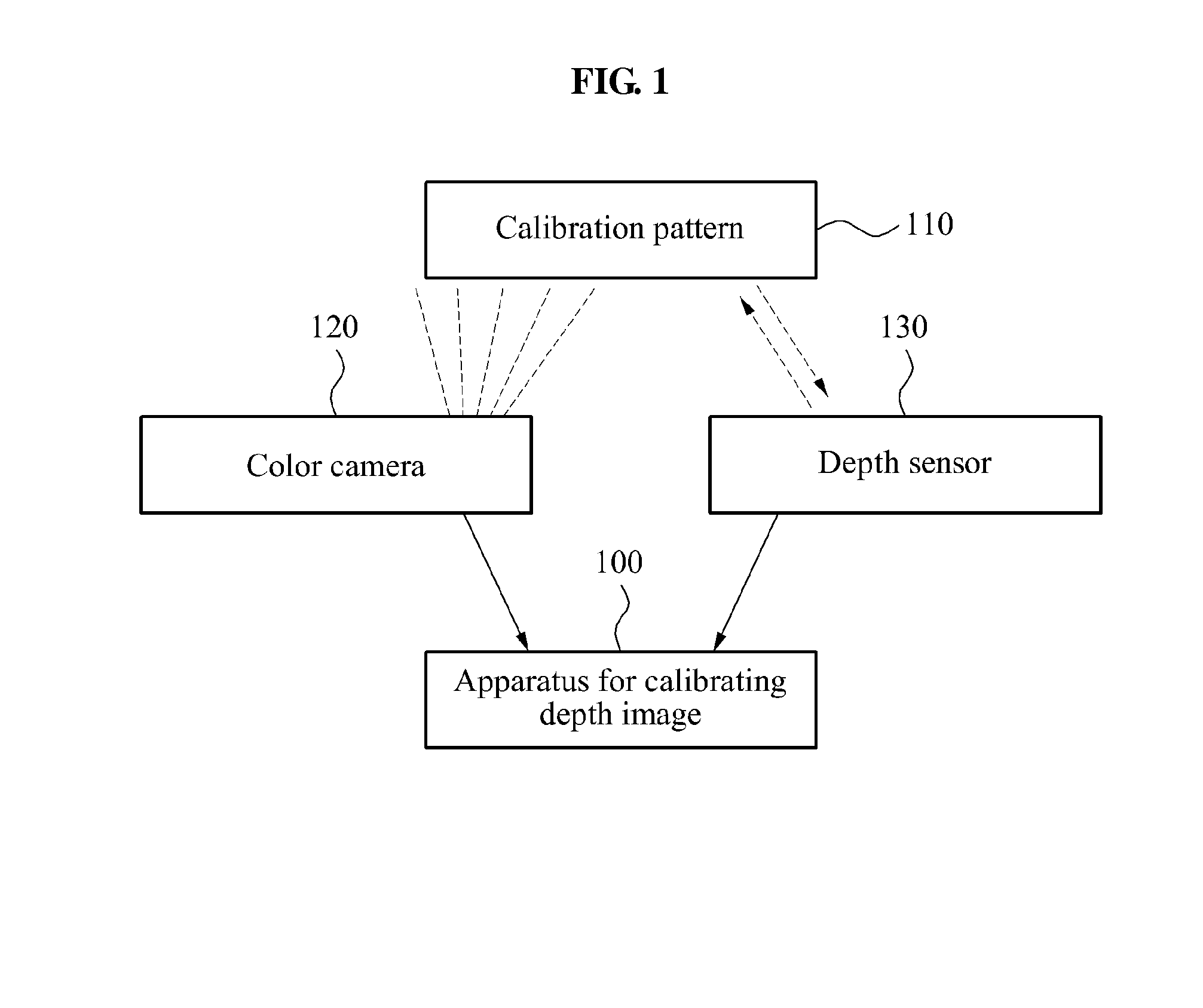
[0029]FIG. 1 is a diagram illustrating a relationship between an apparatus 100 for calibrating a depth image and other apparatuses according to an embodiment of the present invention.

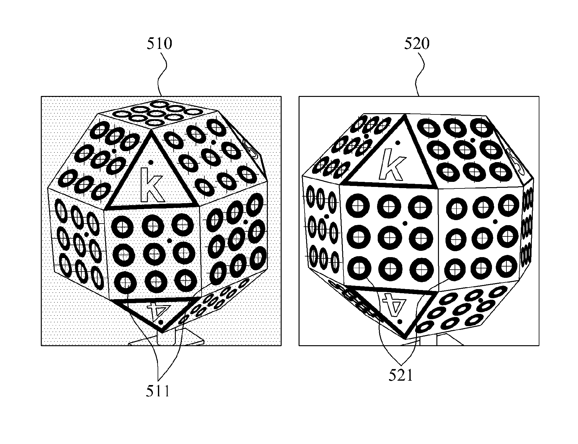
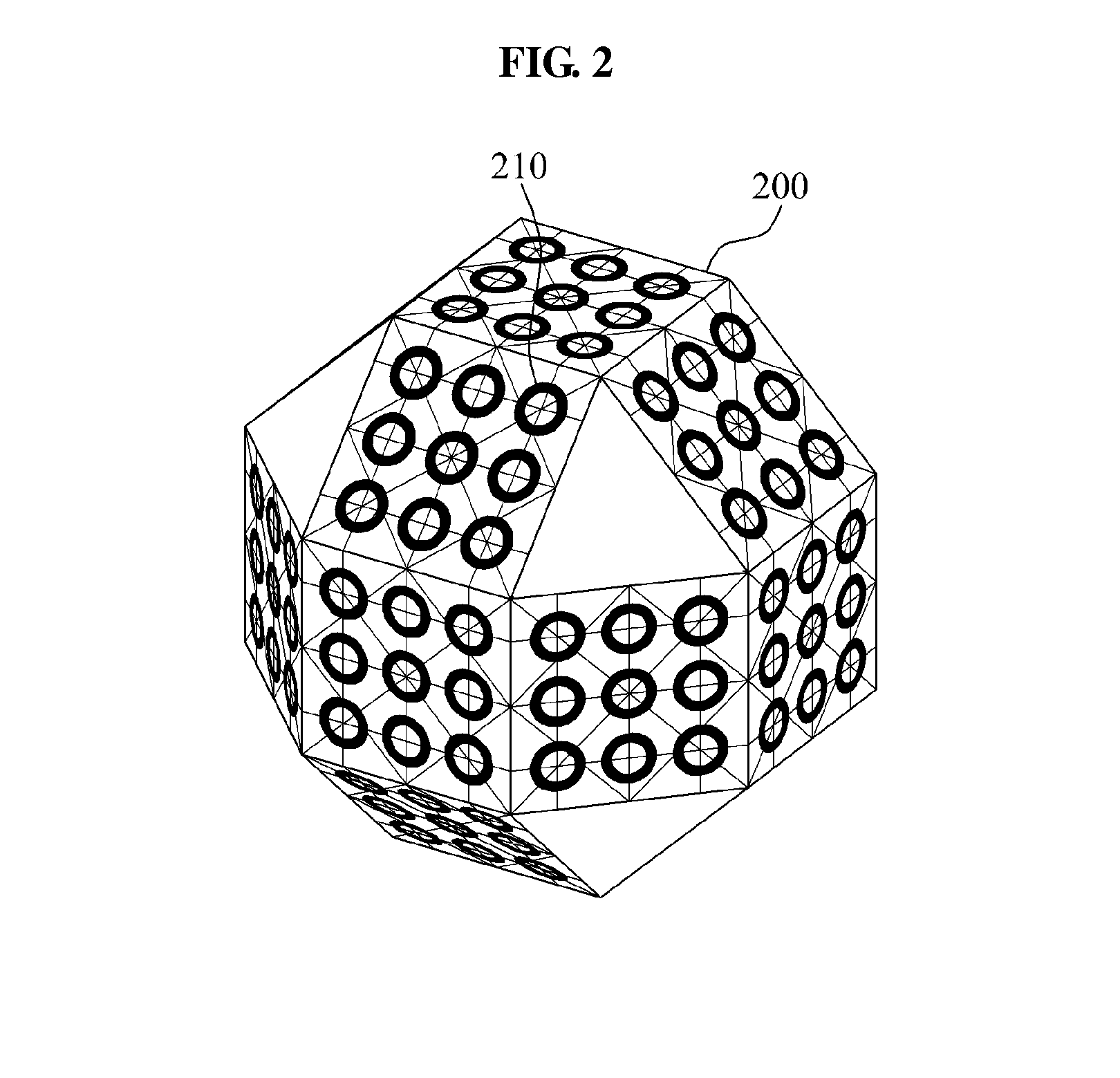
[0030]A color camera 120 may capture a calibration pattern 110 and create a camera image in which the calibration pattern 110 is included. In this example, the calibration pattern 110 may correspond to a three-dimensional (3D) object of which a surface is formed by a plurality of signs, such that a geometric relationship between the color camera 120 and a depth sensor 130 may be readily identified.

[0031]A form of the calibration pattern 110 will be described in detail with refe...


PUM


Abstract

Disclosed is a method of calibrating a depth image based on a relationship between a depth sensor and a color camera, and an apparatus for calibrating a depth image may include a three-dimensional (3D) point determiner to determine a 3D point of a camera image and a 3D point of a depth image simultaneously captured with the camera image, a calibration information determiner to determine calibration information for calibrating an error of a depth image captured by the depth sensor and a geometric information between the depth sensor and a color camera, using the 3D point of the camera image and the 3D point of the depth image, and a depth image calibrator to calibrate the depth image based on the calibration information and the 3D point of the depth image.

Description

CROSS-REFERENCE TO RELATED APPLICATIONS[0001]This application claims the priority benefit of Korean Patent Application No. 10-2012-0117997, filed on Oct. 23, 2012, and Korean Patent Application No. 10-2013-0105538, filed on Sep. 3, 2013, in the Korean Intellectual Property Office, the disclosures of which are incorporated herein by reference.BACKGROUND[0002]1. Field[0003]The present invention relates to an apparatus and method for calibrating a depth image, and more particularly, to an apparatus and method for calibrating a depth image based on a relationship between a depth sensor and a color camera.[0004]2. Description of Related Art[0005]A depth sensor performing triangulation using a structured light, for example, Microsoft Kinect, may obtain a result including an error when employed by an end user, due to assembly tolerances during production and errors in optical portions.[0006]Also, a geometric relationship between a depth sensor and a camera may need to be obtained when a te...

Claims


Application Information

Patent Timeline
Patent Type & Authority Applications(United States)
IPC IPC(8): G06T7/00
CPCG06T7/002G06T2207/10004G06T2207/10028G06T2207/30208G06T7/80
Inventor KIM, JAE HEANCHU, CHANG WOOPARK, IL KYUCHA, YOUNG MICHOI, JIN SUNGKOO, BON KI
Owner ELECTRONICS & TELECOMM RES INST
Learn More