Hybrid Vehicle

a hybrid vehicle technology, applied in the field of hybrid vehicles, can solve the problems of affecting the operation of the vehicle, the diameter of the portion being enlarged, and the difficulty of providing the ev mode or the regenerative mode without involving the rotation of the crank sha

Active Publication Date: 2014-04-24
KUBOTA LTD
View PDF10 Cites 27 Cited by
  • Summary
  • Abstract
  • Description
  • Claims
  • Application Information

AI Technical Summary

Benefits of technology

[0031]With the above-described arrangement, on one side across the belt stepless speed changer device, the engine is disposed and on the side opposite it, the motor is disposed. And, for the belt stepless speed changer device, the driving power of the engine is inputted to one side thereof, and the driving power of the motor is inputted to the other side thereof. Generally, some spare space is often present on the side of the belt stepless speed changer device opposite the engine, where the motor can be disposed easily.
[0033]According to one preferred embodiment of the present invention, a drive shaft of the motor is disposed coaxially with the first shaft member, so that the drive shaft and the first shaft member are rotated in unison. That is, according to this embodiment, there is no need to provide separately a power transmission mechanism or the like for power transmission from the motor to the belt stepless speed changer device. So, the configuration can be formed simple.
[0034]According to another preferred embodiment of the present invention, the hybrid vehicle further comprises a support bracket for rotatably supporting an end of the first shaft member on the side of the motor, and the motor is mounted to the support bracket. Namely, according to this embodiment, the motor can be mounted in a reliable manner with utilization of the support bracket for the first shaft member.
[0042]With the above-described arrangement, even when the output shaft of the engine is stopped or rotated at a low speed, irrespectively of a disengaged state of the clutch, it is still possible to provide the hybrid function by the motor generator and the arrangement between the clutch and the stepless speed changer mechanism can be formed compact.

Problems solved by technology

In the technique disclosed in Japanese Unexamined Patent Application Publication No. 2003-080956, since the motor is mounted between the outer circumference of the clutch outer which is a driven side member of the centrifugal clutch and the inner circumference of the centrifugal clutch accommodating section, there is the problem of the diameter of this portion being enlarged.
Hence, it is difficult to provide the EV mode or the regenerative mode without involving rotation of the crank shaft.

Method used


Image

  • Hybrid Vehicle
  • Hybrid Vehicle
  • Hybrid Vehicle

Examples


first embodiment

[0065]Next, an embodiment of the present invention will be described with reference to the accompanying drawings. Here, there will be described an exemplary case in which this hybrid system is applied to a utility vehicle as an example of a work vehicle, which in turn is an example of a hybrid vehicle.

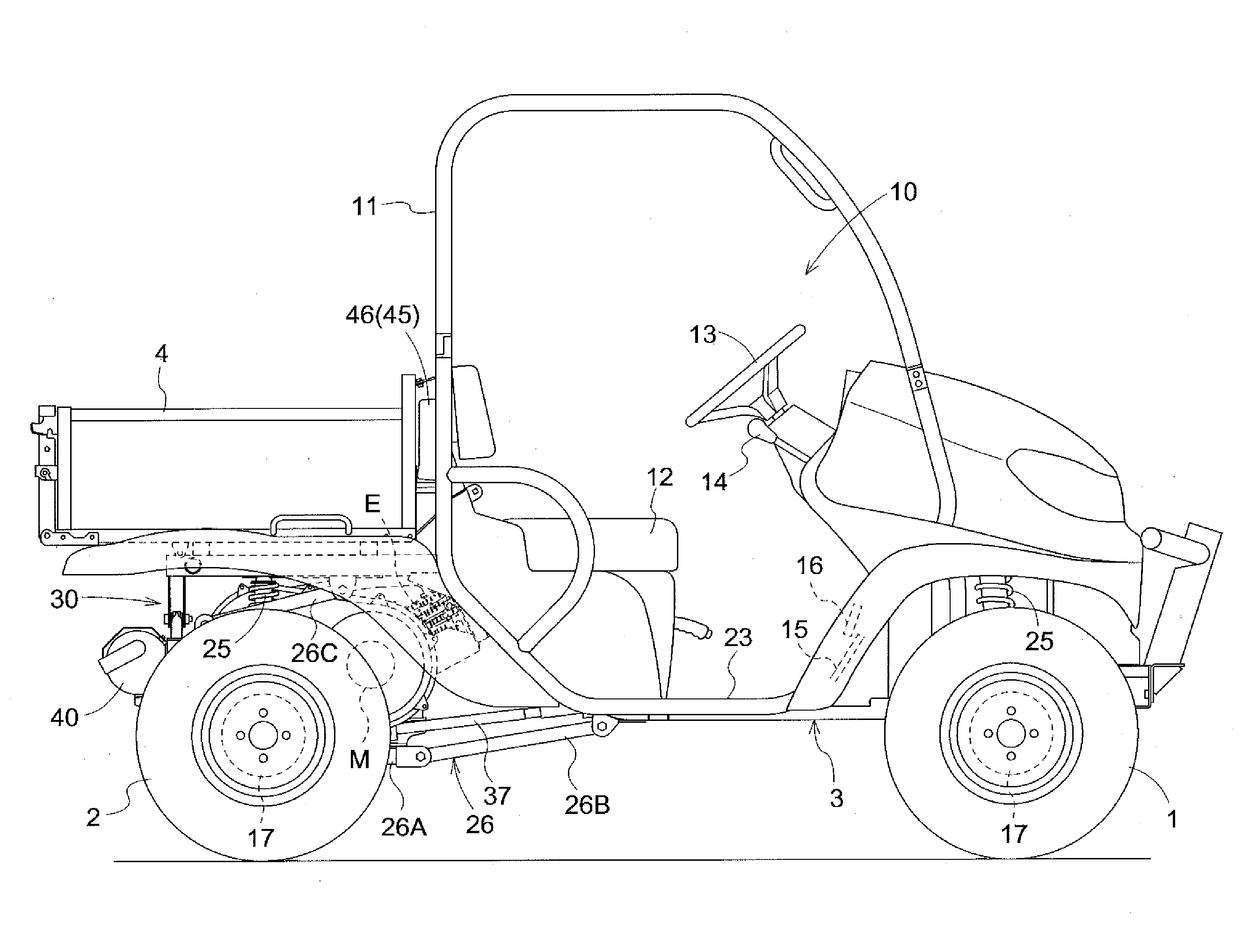
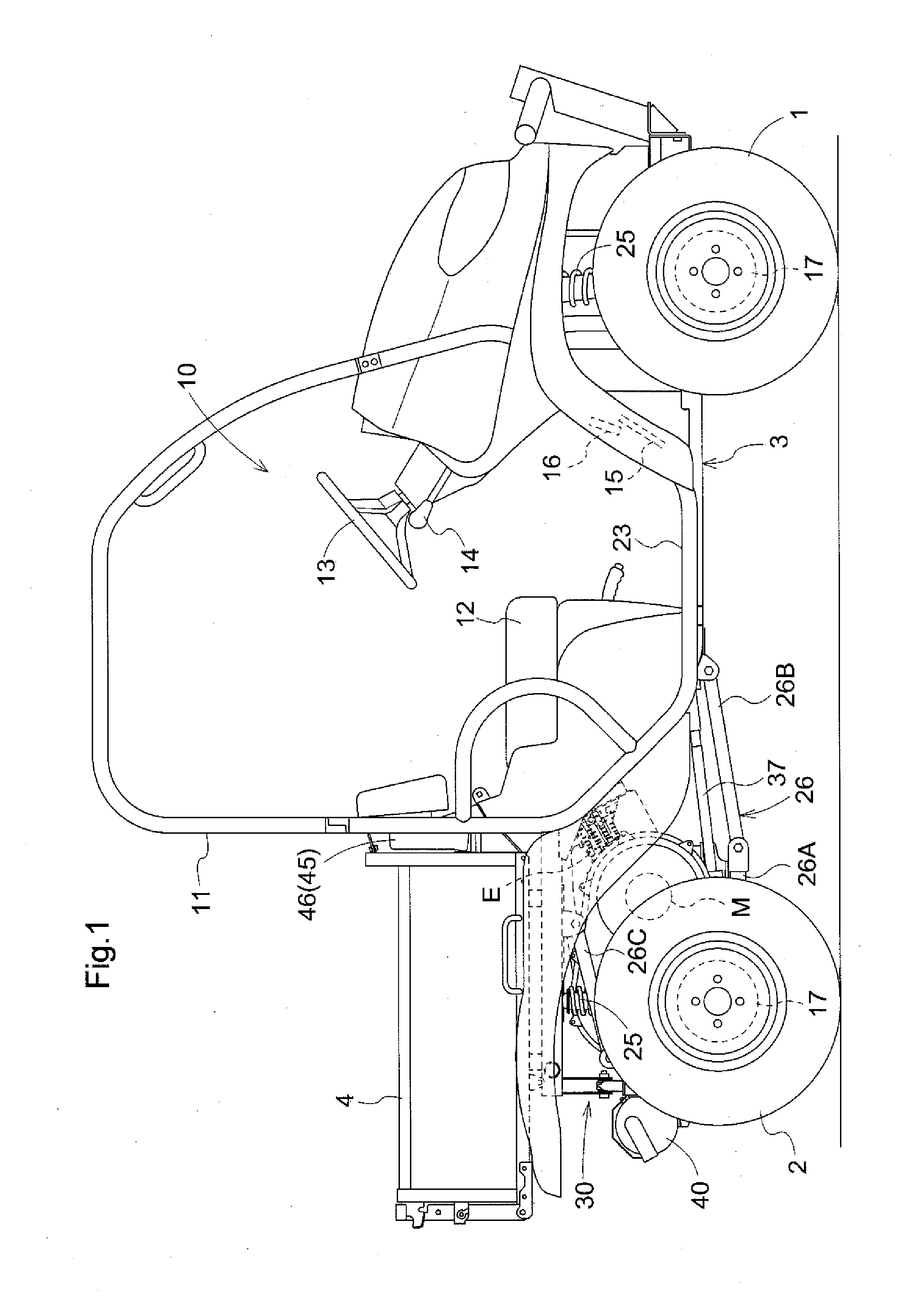
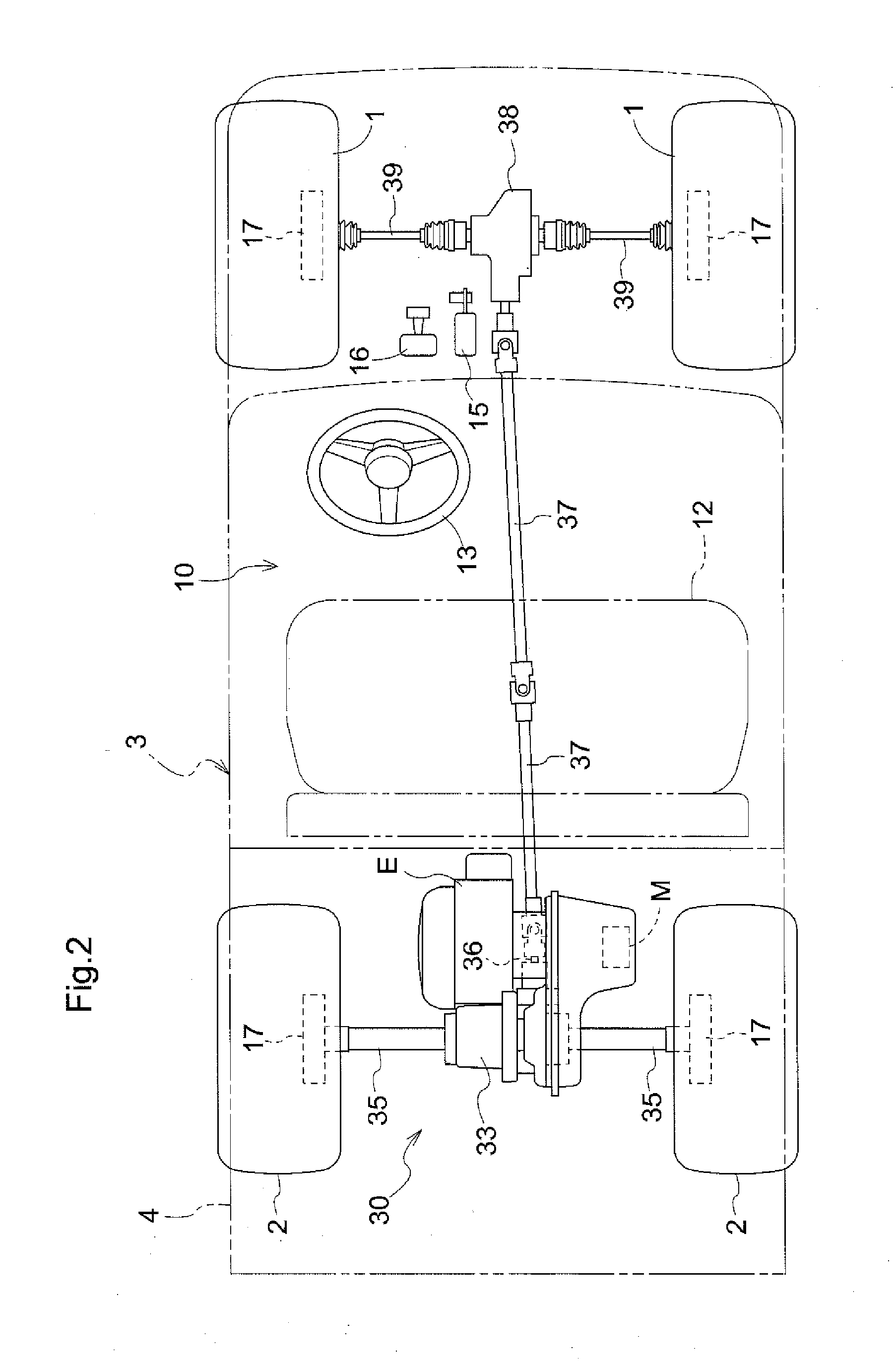
[0066]As shown in FIG. 1 and FIG. 2, in a utility vehicle (will be referred to as “a work vehicle” hereinafter), a pair of left and right steerable front wheels 1 and a pair of left and right rear wheels 2 are mounted on a vehicle body 3 and a driver's section 10 is provided at the center of this vehicle body 3 and a load carrier 4 is provided at the rear portion of the vehicle body 3. And, at a position downwardly of this load carrier 4, an engine section 30 is provided.

[0067]This work vehicle is configured as a four-wheel drive type wherein the driving power from the engine section 30 is transmitted to the front wheels 1 and the rear wheels 2 and the vehicle may be used in works for ...

second embodiment

[0101]Next, an embodiment of the present invention will be described with reference to the accompanying drawings.

[0102]In FIGS. 5-9, there is shown a hybrid system 201 usable as an engine section to be mounted downwardly of a load carrier of a four-wheel drive work vehicle.

[0103]This hybrid system 201 is configured as a power transmission apparatus for transmitting powers of an engine E and a motor generator 208 to a transmission M via a stepless speed changer mechanism 205.

[0104]To the side face of the engine E from which a crank shaft 203 (an output shaft) projects, there are connected a body 220a of an oil pump 220 and a clutch casing 204a of a clutch 204. And, to this clutch casing 204a, a motor case 208a of the motor generator 208 is fixed and to this motor case 208a, the input side of a speed changer case 219 of the stepless speed changer mechanism 5 is fixed.

[0105]As the engine E, there is employed a single cylinder air-cooled OHC type engine, and its crank shaft 203 extends ...

third embodiment

[0151]Next, a third embodiment of the present invention will be described with reference to the accompanying drawings.

[0152]In FIGS. 10 and 11, there is shown a driving apparatus 301 for a traveling vehicle applicable as an engine section mounted downwardly of a load carrier of a four-wheel drive work vehicle.

[0153]This driving apparatus 301 for a traveling vehicle is configured as a power transmission apparatus for transmitting powers of an engine E and a motor generator 308 to a transmission T via a stepless speed changer mechanism 5. The speed changer mechanism 5 is a belt stepless speed changer mechanism (CVT).

[0154]To the side face of the engine E from which an output shaft (crank shaft) 303 projects, there are connected a body 320a of an oil pump 320 and a clutch casing 304a of a clutch 304. And, to this clutch casing 304a, a motor case 308a of the motor generator 308 is fixed and to this motor case 308a, the input side of a speed changer case 319 of the stepless speed changer...


PUM


Abstract

A hybrid vehicle includes an engine, a motor, and a belt stepless speed changer device having a driving rotary body, a driven rotary body, a first shaft member supporting the driving rotary body with allowing rotation thereof in unison, a second shaft member supporting the driven rotary body with allowing rotation thereof in unison, and an endless belt wound around the driving rotary body and the driven rotary body. The vehicle further includes a transmission case configured to receive the powers from the engine and the motor via the belt stepless speed changer device and a centrifugal clutch incorporated in a power transmission line extending form the engine to the first shaft member. The motor is disposed on the side opposite the engine across the driving rotary body, and the driving power of the motor is inputted to the first shaft member.

Description

CROSS-REFERENCE TO RELATED APPLICATION[0001]This application claims priority to Japanese Patent Application Nos. 2012-231869 filed Oct. 19, 2012, 2013-002885 filed Jan. 10, 2013, and 2013-126687 filed Jun. 17, 2013, the disclosures of which are hereby incorporated in their entirety by reference.BACKGROUND OF THE INVENTION[0002]1. Field of the Invention[0003]The present invention relates to a hybrid vehicle having an engine and a motor.[0004]2. Description of the Related Art[0005]For vehicles such as automobiles, for the purpose of seeking improvement in fuel consumption economy and reduction of exhaust gas amount, there is proposed a hybrid vehicle having a motor for providing auxiliary power, in addition to a gasoline engine.[0006]Japanese Unexamined Patent Application Publication No. 2003-080956 discloses an engine unit for a starter, having an engine, a motor, a belt stepless speed changer, etc. In this engine unit, a drive pulley is mounted on a crank shaft of the engine and a l...

Claims


Application Information

Patent Timeline
Patent Type & Authority Applications(United States)
IPC IPC(8): B60W20/00F16H9/12
CPCB60W20/30Y10S903/902F16H9/125F16H9/18B60K6/383B60K6/387B60K6/405B60K6/52B60K6/543B60W10/02B60W10/06B60W10/08B60K2006/4816B60W2510/0638Y10S903/913Y10S903/914Y10S903/918Y10S903/945Y10S903/946Y10S903/947B60K6/48Y02T10/62B60W10/04B60W10/18B60W2540/10B60W2540/12B60W2710/021B60Y2200/92B60Y2300/42B60Y2306/05
Inventor YAGYU, SUMIOTAKAKI, GOKAWABATA, SHINICHIHAYASHI, SHIGEKINAKAI, SHOHEIBESSHO, HIROKI
Owner KUBOTA LTD
Why Eureka
Try Eureka