Spraying Device

a technology of spraying device and spraying chamber, which is applied in the direction of water installations, disinfection, construction, etc., can solve the problems of contaminating the available surface of the toilet, serious health problems, and high undesirable deposition of pathogenic microorganisms or viruses, and achieves the effect of convenient us

Active Publication Date: 2014-05-01
CONOPCO INC D B A UNILEVER
View PDF14 Cites 36 Cited by
  • Summary
  • Abstract
  • Description
  • Claims
  • Application Information

AI Technical Summary

Benefits of technology

[0012]Another object of the invention is to provide a device that reduces the chance that a user of the toilet comes in contact with airborne micro-organisms and viruses and/or disinfecting or sanitising fluid. Anoth

Problems solved by technology

The bacterial mist can remain airborne for over two hours, floating around in the air and spreading over the room to finally settle on and thus contaminating the available surfaces around the toilet.
This spread of faeces originating bacteria and/or viruses over the bathroom is undesirable with respect to hygiene and could even cause serious health problems.
Examples of surfaces on which deposition of pathogenic micro-organisms or viruses is highly undesirable are toothbrushes, hairbrushes, light switches, and the toilet paper.
The disadva

Method used


Image

  • Spraying Device
  • Spraying Device
  • Spraying Device

Examples


example 1

[0112]In this example experiments were carried out so as to find the beneficial effect of the spraying device of the invention when compared with a spraying device having simultaneous pumping and nozzle rotating action.

[0113]To this end, the electric power consumed by a prototype spraying device of the invention (having sequential pumping and rotating action) as well as a comparative spraying device (having simultaneous pumping and rotating action) was measured.

[0114]The following results were obtained:

Pump configurationPeak power consumedEfficiencySimultaneous pump & rotate5.5 watt23%Sequential pump & rotate4.5 watt28%

[0115]It follows from the above results that the sequential system according to the invention is more efficient and requires 1 watt less power that the simultaneous system of the prior art. This significant benefit is unexpected as the rotating nozzle requires only very little power to rotate.

example 2

[0116]In this example, experiments have been carried out with a spraying device of the invention (producing an aerosol having an average Dv50 particle size of 50 microns) as well as a modified spraying device. The aerosol produced by the modified spraying device has an (much higher) average Dv50 particle size of 100 microns. It is further noted that this modified spraying device only differs from the spraying device of the invention with regard to the average particle size of the aerosol produced.

[0117]A test was designed to check if the sprayed aerosol delivered by each of these spraying devices is able to reach and disinfect the under the rim area of the internal surface of a toilet bowl. It was chosen to test the coverage under the rim as this part of the toilet surface is generally difficult to be reached by the sprayed aerosol. For this test, test slides containing a 4 log escheria coli bacteria culture were positioned in the cavity under said rim.

[0118]Furthermore the followin...


PUM


Abstract

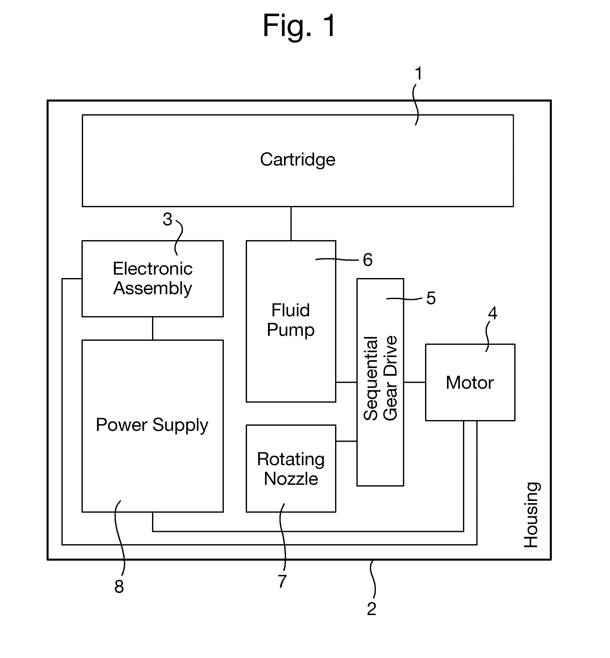
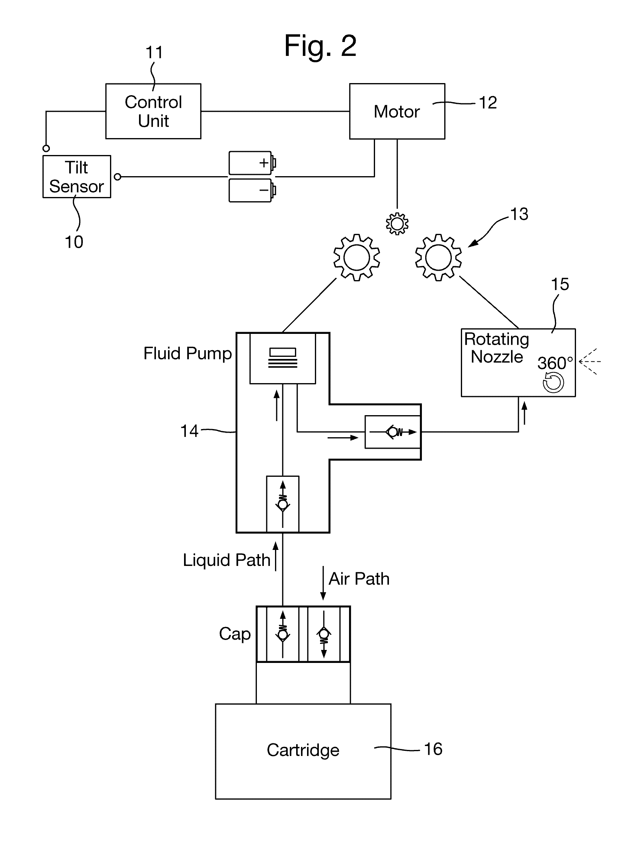
The present invention relates to a automated spraying device for spraying an enclosure with a liquid cleanser, the device having, a reservoir (16) for containing the liquid cleanser, a pump (14) in fluid communication with the reservoir, and a movable spray head (15) having an outlet orifice through which cleanser from the reservoir can be expelled during operation of the pump if there is such liquid cleanser in the reservoir. Said spraying device also contains an electrical motor drive mechanism (12) for sequentially operating th pump (14) and moving the spray head (15) to modify the direction of the spray there from, such that the spray head is not simultaneously spraying and moving. Furthermore, the spray head is suitable for producing an aerosol whereby the Dv50 of the aerosol is in the range of from 30 to 70 micron.

Description

FIELD OF THE INVENTION [0001]The present invention relates to a cleaner spraying device for automatically spraying an enclosure. In particular, the invention relates to a cleaner spraying device which is suited for automatically cleaning a toilet bowl, more specifically for treatment of micro-organisms and viruses that become airborne in the inner volume of the toilet bowl during flushing.BACKGROUND OF THE INVENTION[0002]It is well known that every time the toilet is flushed after use, thousands of bacteria and virus particles are catapulted into the air, travelling as far as two meters or more out of and up from the toilet bowl as a fine invisible mist. An existing hypothesis refers to the greatest bacterial mist dispersal occurring not during the initial moments of the flush, but rather once most of the water has already left the bowl.[0003]The bacterial mist can remain airborne for over two hours, floating around in the air and spreading over the room to finally settle on and thu...

Claims


Application Information

Patent Timeline
IPC IPC(8): E03D9/00
CPCE03D9/005A61L2/22A61L9/14A61L2209/111A61L2209/133B05B3/02B05B9/0861
Inventor CARPENTER, MATTHEW CHACEFOCHT, KENNETH ALLENPASQUINI, FEDERICOPIETRASANTA, DAVIDESORZE, ANDREA DIAS
Owner CONOPCO INC D B A UNILEVER
Why Eureka
Try Eureka