Gravitational settling tank and method for producing ash-free coal

Active Publication Date: 2014-05-01
KOBE STEEL LTD
View PDF2 Cites 1 Cited by
  • Summary
  • Abstract
  • Description
  • Claims
  • Application Information

AI Technical Summary

Benefits of technology

[0022]According to the present invention, the slurry supply pipe includes the nozzle part extending in the horizontal direction, and the nozzle part includes the plurality of holes. It is thus possible to uniformly eject the slurry from the plurality of holes into the pressure vessel and to inhibit the agitation of the solid-content concentrated liquid settled in the bottom. This results in the efficient production of ash-free coal in which ash is sufficiently removed.

Problems solved by technology

The flow of the slurry concentrates at a point, thus disadvantageously agitating the solid-content concentrated liquid settled in the lower portion of the gravitational settling tank.

Method used


Image

  • Gravitational settling tank and method for producing ash-free coal
  • Gravitational settling tank and method for producing ash-free coal
  • Gravitational settling tank and method for producing ash-free coal

Examples


modified embodiment

[0043](a) and (b) in FIG. 4 are perspective views of gravitational settling tanks according to modified embodiments of the present invention. Slurry supply pipes different in shape from that in the foregoing embodiment are provided. In each of (a) and (b) in FIG. 4, for the sake of easy understanding of the internal structure, part of the gravitational settling tank 3 is illustrated in perspective. In a gravitational settling tank 3a illustrated in FIG. 4(a), nozzle parts 22a are arranged so as to be divided into two directions from an end of a main body part 21a of a slurry supply pipe 15a. A bent portion 24a and an outlet 25a are provided at an end portion of each of the nozzle parts 22a. Each of the two outlets 25a is located at a position distant from the end of the main body part 21a by almost half the circumference. In a gravitational settling tank 3b illustrated in FIG. 4(b), a main body part 21b of a slurry supply pipe 15b is arranged so as to pass roughly through the center...

examples

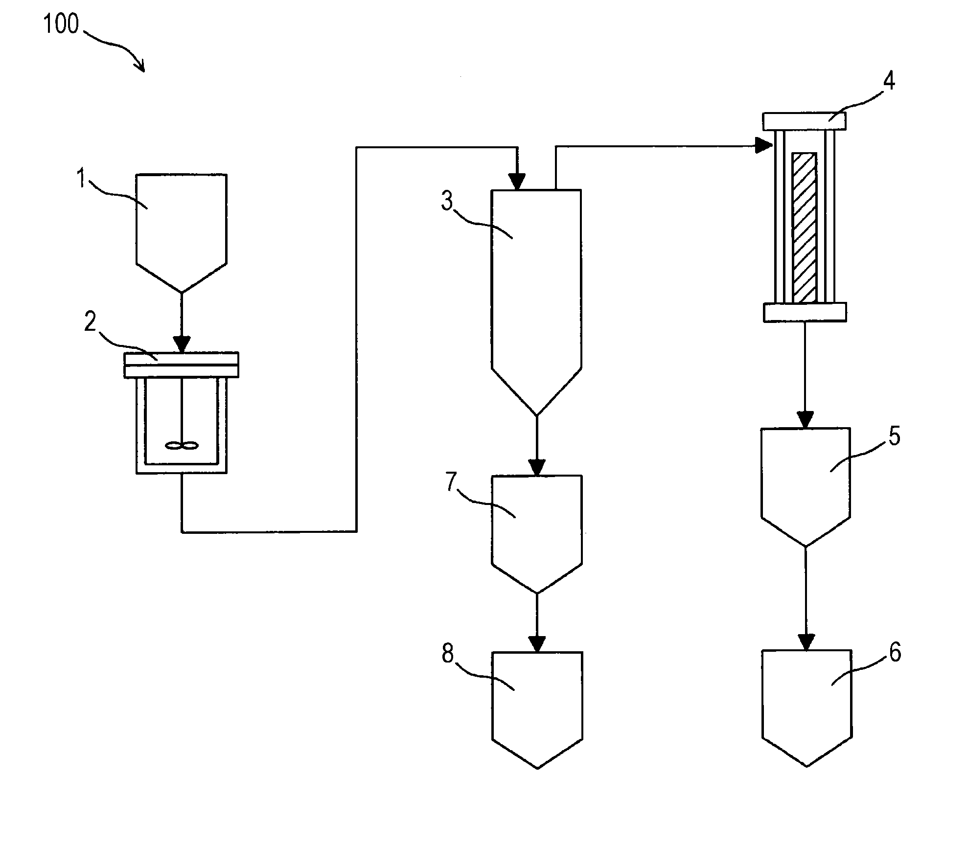
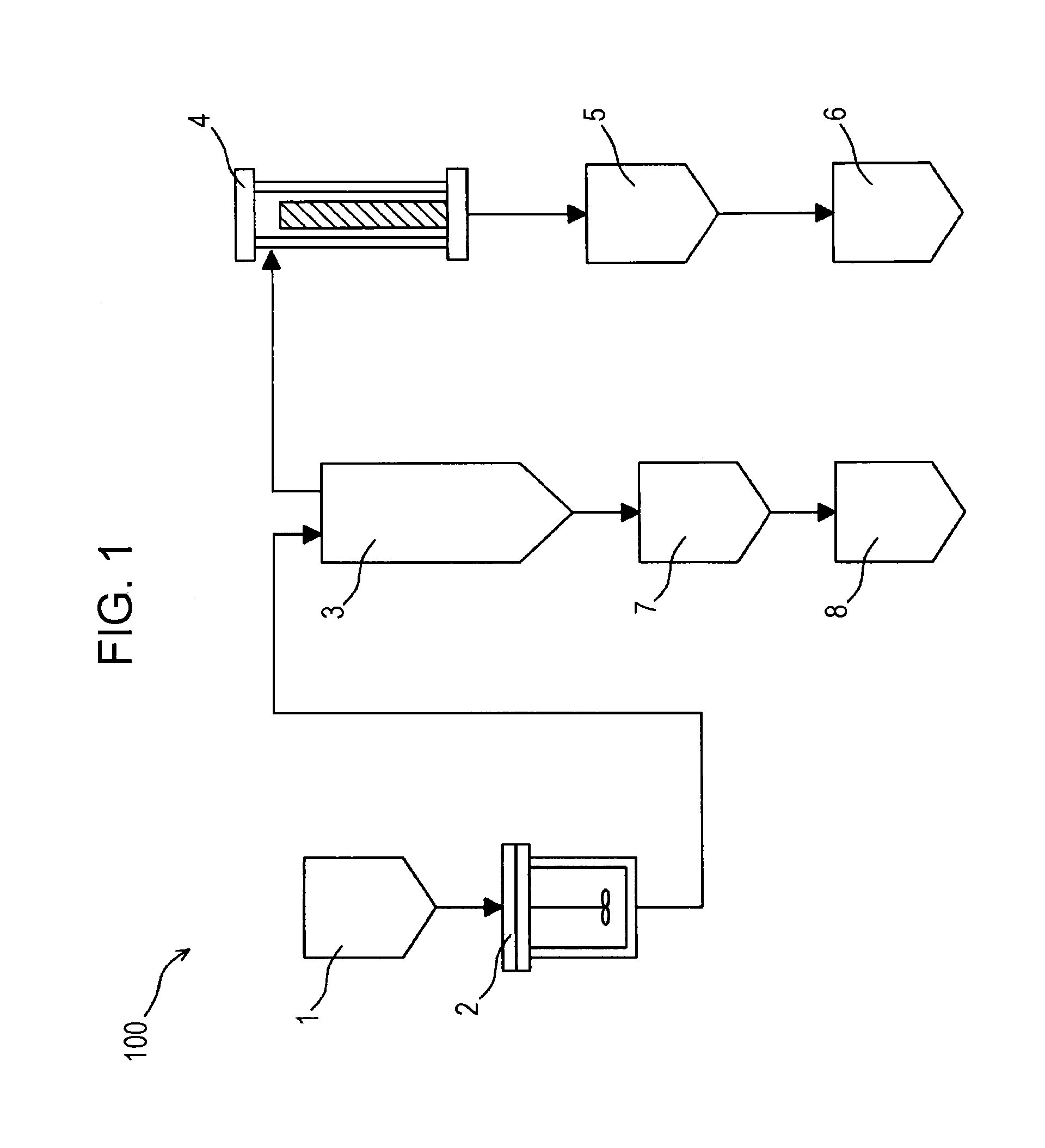
[0059]To check a gravitational settling tank according to the present invention, an experiment was conducted with a gravitational settling tank having the same structure as the gravitational settling tank 3 according to the present invention illustrated in FIG. 1 and a conventional gravitational settling tank. In this experiment, solid concentration distributions in pressure vessels of the two gravitational settling tanks are measured and compared with each other after separation into solid matter and a supernatant liquid.

[0060]Bituminous coal is used as a coal feedstock. Methylnaphthalene H (C-Chem Co., Ltd)) is used as a solvent. The coal and the solvent is mixed together to prepare a slurry. The concentration of the coal feedstock with respect to the solvent is 19.5% by weight on a dry coal basis. The slurry was heated to 400° C. and pressurized to 2.0 MPa to extract a soluble component in the solvent for 20 minutes. The slurry was fed to the gravitational settling tank that was ...


PUM

PropertyMeasurementUnit
pressureaaaaaaaaaa
pressureaaaaaaaaaa
temperatureaaaaaaaaaa

Abstract

A gravitational settling tank including a pressure vessel which precipitates solid content contained in slurry in which coal and solvent are blended, and separates the solid-content concentrated liquid from the supernatant liquid, and a supply pipe which supplies the pressure vessel with the slurry. A main body part and a nozzle part which is connected on the downstream side of the main body part and extends horizontally are provided in the supply pipe. A plurality of holes are provided in the nozzle part. By virtue of this, agitation of the solid-content concentrated liquid which has settled in the bottom is inhibited.

Description

TECHNICAL FIELD[0001]The present invention relates to a gravitational settling tank configured to allow a slurry containing coal and a solvent to be separated into a solid-content concentrated liquid and a supernatant liquid, and a method for producing ash-free coal in which ash is removed from coal.BACKGROUND ART[0002]Coal has been extensively used as a fuel for thermal power generation and boilers or a raw material for chemicals. As one of the environmental measures, there has been a strong demand for the development of a technique for efficiently removing ash in coal. For example, in a high-efficiency hybrid power system using gas turbine combustion, an attempt has been made to use ash-free coal, in which ash is removed, as an alternative fuel to a liquid fuel, such as LNG.[0003]In a known method as a method for producing ash-free coal (for example, PTL 1), a slurry prepared by mixing coal and a solvent is heated to extract a coal component soluble in the solvent (hereinafter, re...

Claims


Application Information

Patent Timeline
Patent Type & Authority Applications(United States)
IPC IPC(8): C10L9/10B01D21/24
CPCC10L9/10B01D21/2405C10L9/02B01D21/2416B01D21/2427B01D21/24C10L5/00
Inventor SAKAI, KOJISHISHIDO, TAKAHIROOKUYAMA, NORIYUKIHAMAGUCHI, MAKI
Owner KOBE STEEL LTD
Why Eureka
Try Eureka