
Permeameter for in-situ measurement of saturated hydraulic conductivity

a technology of in-situ measurement and saturated hydraulic conductivity, which is applied in the direction of instruments, suspensions, porous material analysis, etc., can solve the problems of reduced reliability of measurement methods using standpipe and seepage meters, and may ignore the velocity head, etc., and achieve high reliability

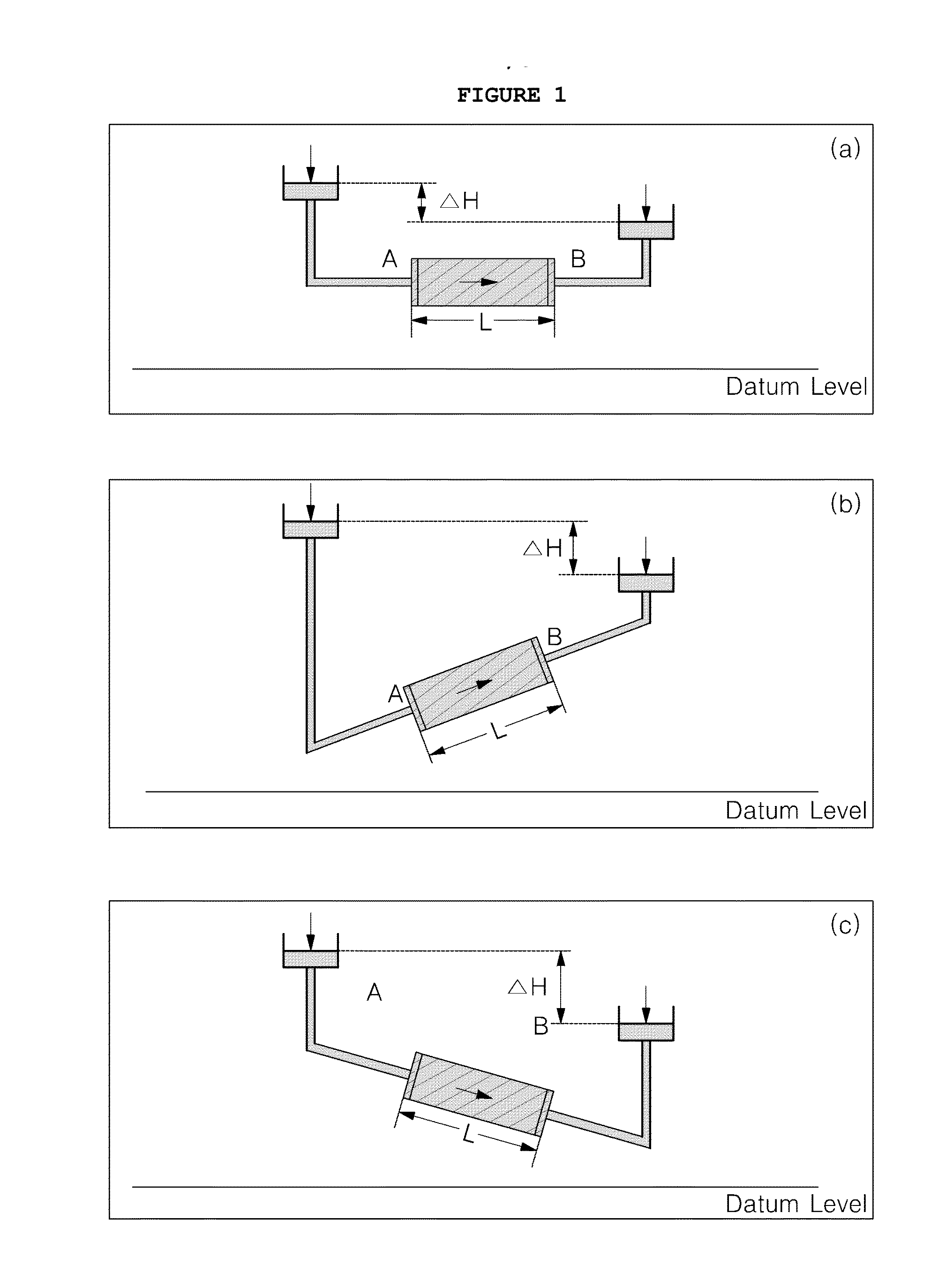
Active Publication Date: 2014-05-01
KOREA INST OF GEOSCI & MINERAL RESOURCES
View PDF1 Cites 11 Cited by
  • Summary
  • Abstract
  • Description
  • Claims
  • Application Information

AI Technical Summary

Benefits of technology

The invention proposes an apparatus for measuring the hydraulic conductivity of sediment at the water-sediment interface with high reliability. The apparatus includes a chamber and a storage pipe that create a hydraulic head difference, allowing groundwater to flow from the lower side to the upper side within the chamber. This results in the effective measurement of the hydraulic conductivity of the sediment by measuring the amount of water flowing through the chamber. Overall, this technology helps to accurately measure hydraulic conductivity in sediment in real-life settings.

Problems solved by technology

However, the velocity head may be ignored because generally the flow of groundwater is very slow.
However, it has been reported that methods using the standpipe and seepage meter have problems of reduced reliability in terms of measuring results, the slug test has problems in that only horizontal hydraulic conductivity can be obtained, and the grain size analysis method has problems of using empirical formulae (Landon et al., 2001).
However, an apparatus and method of in-situ measuring of saturated hydraulic conductivity which causes water to flow upwards through sediment within chamber or pipe with or without power are not yet provided.

Method used


Image

  • Permeameter for in-situ measurement of saturated hydraulic conductivity
  • Permeameter for in-situ measurement of saturated hydraulic conductivity
  • Permeameter for in-situ measurement of saturated hydraulic conductivity

Examples


Embodiment Construction

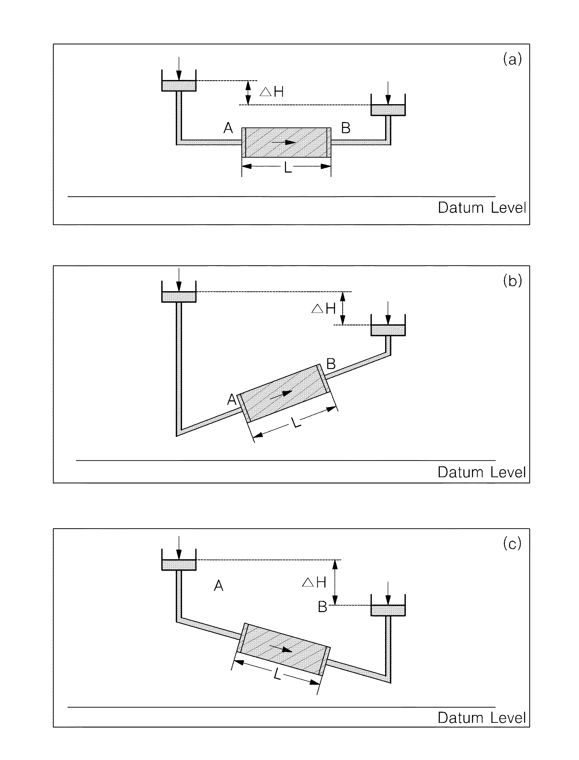
[0027]Prior to describing various embodiments in detail, it will be appreciated that the present invention is not limited to details on construction and arrangement of constitutional elements described in the description or illustrated in the drawings. The present invention may be realized and embodied into other embodiments and may be carried out in a variety of methods. Furthermore, it should be understood that directional terms about an apparatus or elements (such as “front”, “back”, “up”, “down”, “top”, “bottom”, “left”, “right”, “lateral”, or the like) that are used herein are provided in order to merely simplify the description of the invention, and they do not mean that associated apparatus or elements should have such orientations.

[0028]The present invention has the following features for accomplishing the above objects of the invention.

[0029]Hereinbelow, preferred embodiments of the present invention will be described in detail with reference to the accompanying drawings. P...


PUM

PropertyMeasurementUnit
lengthaaaaaaaaaa
lengthaaaaaaaaaa
inner diameteraaaaaaaaaa

Abstract

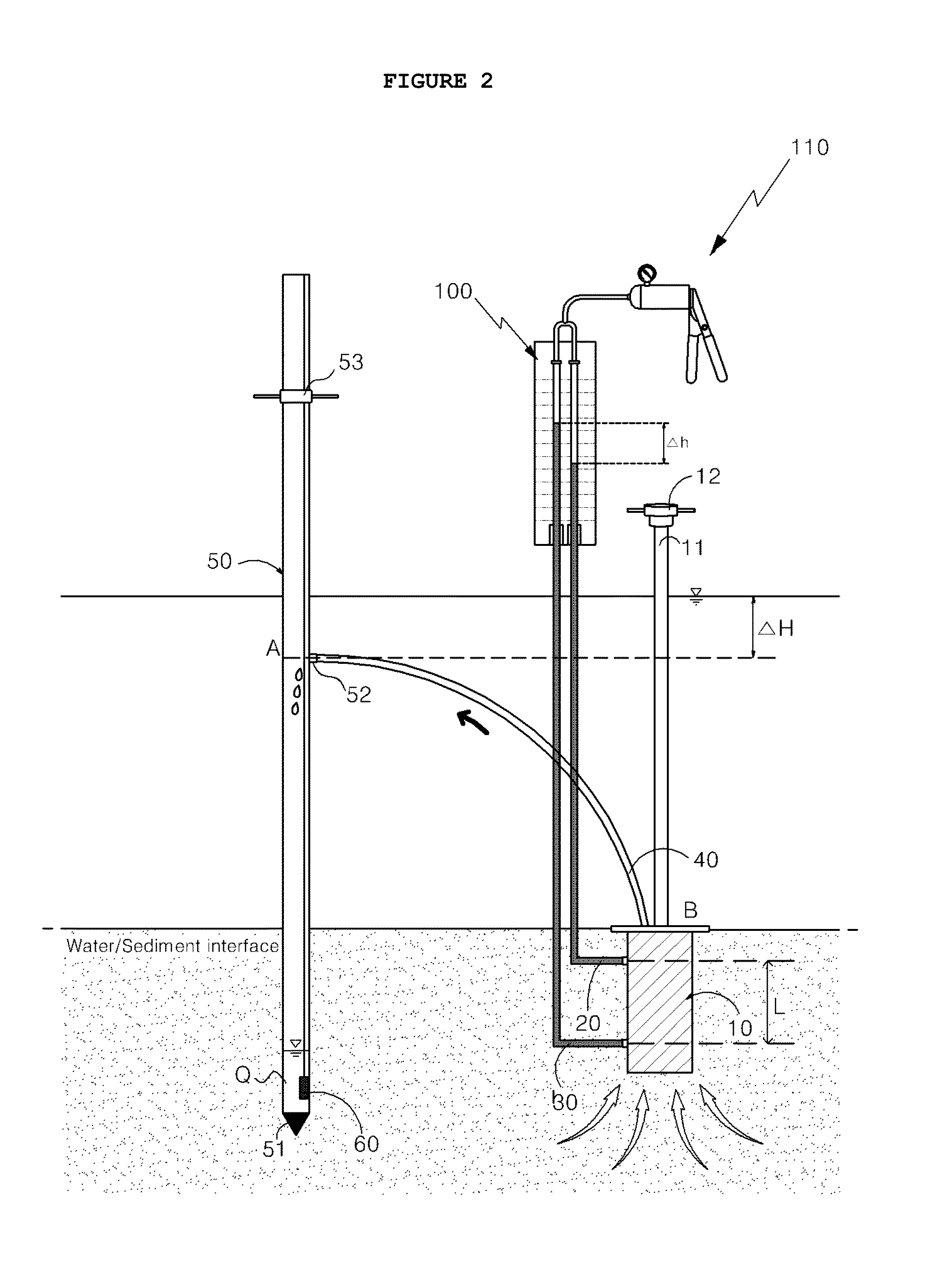
Disclosed is a permeameter for in-situ measurement of saturated hydraulic conductivity. The permeameter includes a chamber fixedly installed into a streambed sediment such that the inside of the chamber is filled with a medium, sediment at water-sediment interface. First and second hydraulic head-measuring lines are respectively connected to upper and lower portions of an outer circumferential surface of the chamber, these are designed for measuring a hydraulic head difference of the inside of the chamber. A flexible tube is interconnected the chamber with the storage pipe. A storage pipe is designed to regulate a hydraulic head difference from the chamber and to measure a quantity and a flow rate of water introduced from the chamber under the streambed.

Description

CROSS-REFERENCE TO RELATED APPLICATIONS[0001]This application claims priority to and the benefit of Korean Patent Application No. 10-2012-0119620 filed in the Korean Intellectual Property Office on Oct. 26, 2012, the entire contents of which are incorporated herein by reference.BACKGROUND OF THE INVENTION[0002]1. Field of the Invention[0003]The present invention relates, in general, to a permeameter for in-situ measurement of saturated hydraulic conductivity of streambed sediments. The head difference between head within the chamber and head at the inlet of the pipe acts as the driving force to flow water from the chamber to the pipe. This head difference can be induced by adjusting the depth of the inlet in the pipe below stream stage. Water in a saturated zone around the chamber flows upwards through the sediments inside the chamber without electric power.[0004]Upward flowing of water within the chamber causes a hydraulic head difference between the upper side and lower side of th...

Claims


Application Information

Patent Timeline
Patent Type & Authority Applications(United States)
IPC IPC(8): G01N15/08
CPCG01N15/082E21B49/00G01N15/0806G01N15/0826G01N33/246E02D1/00E02D1/02G01N15/08G01N33/24
Inventor LEE, BONG JOO
Owner KOREA INST OF GEOSCI & MINERAL RESOURCES
Learn More