Understructure for a vehicle

a technology for vehicle floor and structure, applied in the field of vehicle floor structure, can solve the problems of environmental hazards, high replacement and repair costs, collision behaviour of vehicles in relation, etc., and achieve the effects of reducing production costs, manufacturing effort and expenditure, and flexible but stable connection of longitudinal member elements

Active Publication Date: 2014-05-01
THYSSENKRUPP STEEL EURO AG
View PDF6 Cites 45 Cited by
  • Summary
  • Abstract
  • Description
  • Claims
  • Application Information

AI Technical Summary

Benefits of technology

[0039]The longitudinal member elements can be connected by connecting parts to the longitudinal member. A simple, flexible but stable connection of the longitudinal member elements to the longitudinal members can be produced by means of the connecting parts. The connecting parts can be formed in particular by bent parts. Thus, a complex structural shape can first of all be cut into a sheet, which is then bent at defined bending edges so as to provide a profile that can join longitudinal members and longitudinal member elements. A complex and stable structural part can be produced in a particularly simple manner with bent parts.
[0040]In addition cross members can also be joined to the floor structure via the connecting parts. In particular it is advantageous if the cross members connecting the sills are joined by means of the connecting parts to the longitudinal members and / or longitudinal member elements. In this way a stable connection of the cross member intersecting the longitudinal member or longitudinal member element is achieved.
[0041]According to a further the longitudinal member elements are formed geometrically substantially identically. This reduces the production costs and the manufacturing effort and expenditure, since a distinction does not have to be made between front and rear or left and right longitudinal member elements.
[0042]It is furthermore preferred if the longitudinal member elements are produced by U-O forming and shaping. In this way light but stable longitudinal member elements can be produced. The longitudinal member element can be welded to a closed profile by means of conventional welding or laser welding. Despite their low weight, longitudinal members produced in this way have a high stability and rigidity.
[0043]Finally, according to a second teaching of the invention it is advantageous to use a floor structure according to the invention in a motor vehicle with an electric and / internal combustion engine. A vehicle with an electric and / or internal combustion engine can thus be provided that has an excellent accident behaviour on account of the floor structure. Energy storage modules housed in the accommodating means of the floor structure are effectively protected against damage by impacts, in particular side impacts, without the production costs of the floor structure and its weight being adversely affected.

Problems solved by technology

The problem here however is the accident behaviour of the vehicles in relation to the energy storage modules.
An effective protection of the energy storage modules is however absolutely essential, since on the one hand damage to the energy storage modules results in expensive replacement and repair costs, and on the other hand constitutes an environmental hazard if chemical substances for example from a damaged battery are released into the environment after an accident.

Method used


Image

  • Understructure for a vehicle
  • Understructure for a vehicle
  • Understructure for a vehicle

Examples


Embodiment Construction

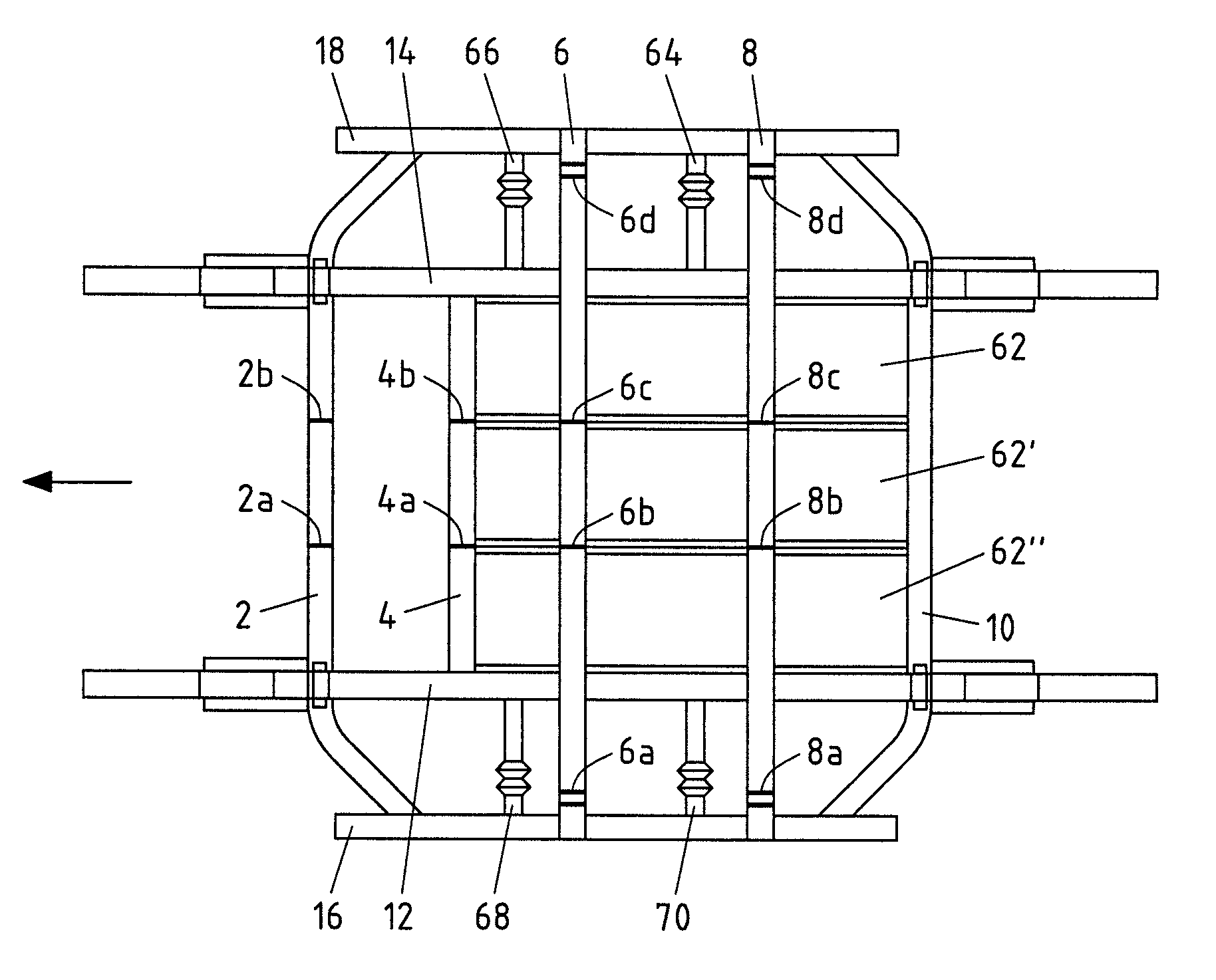
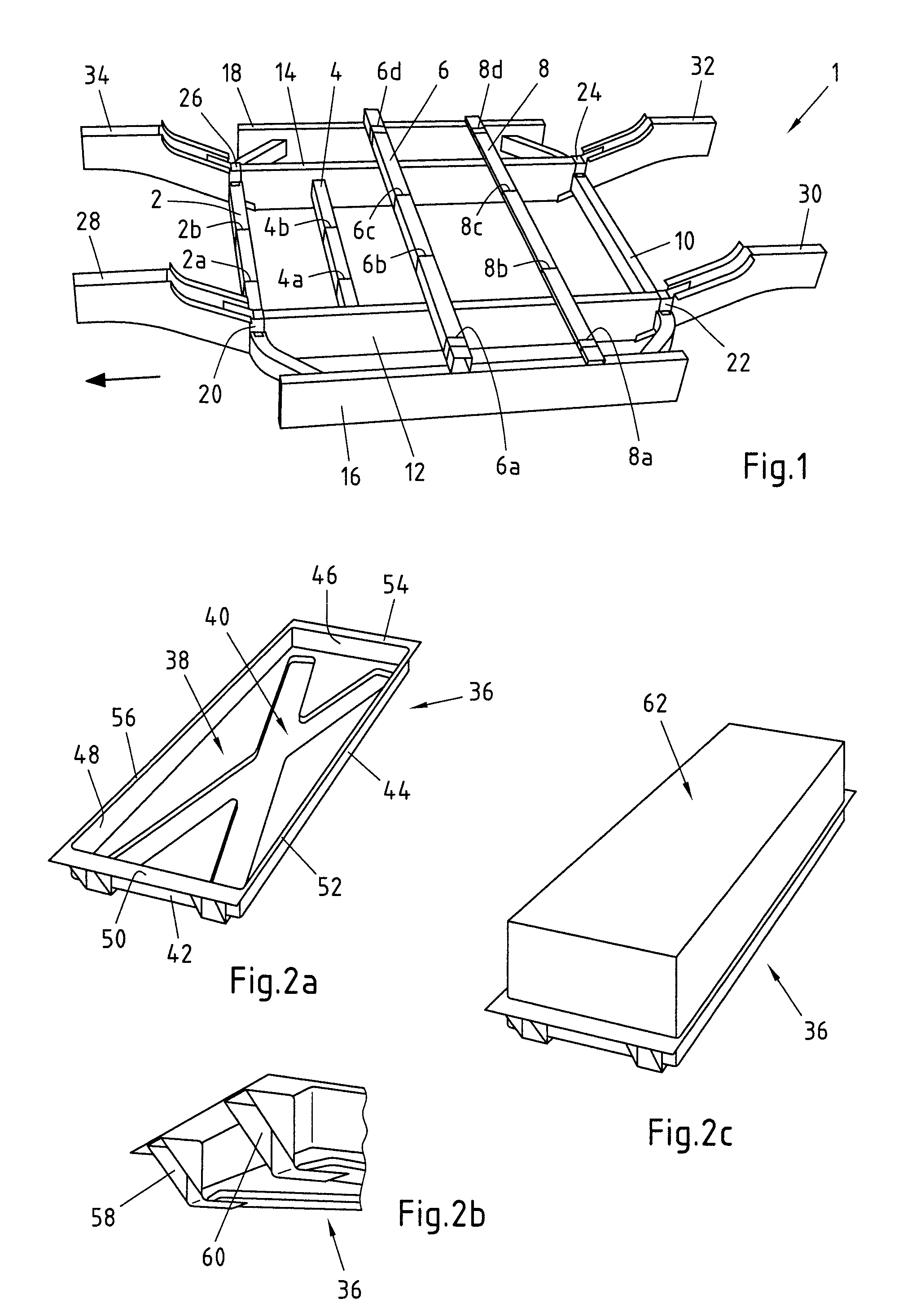
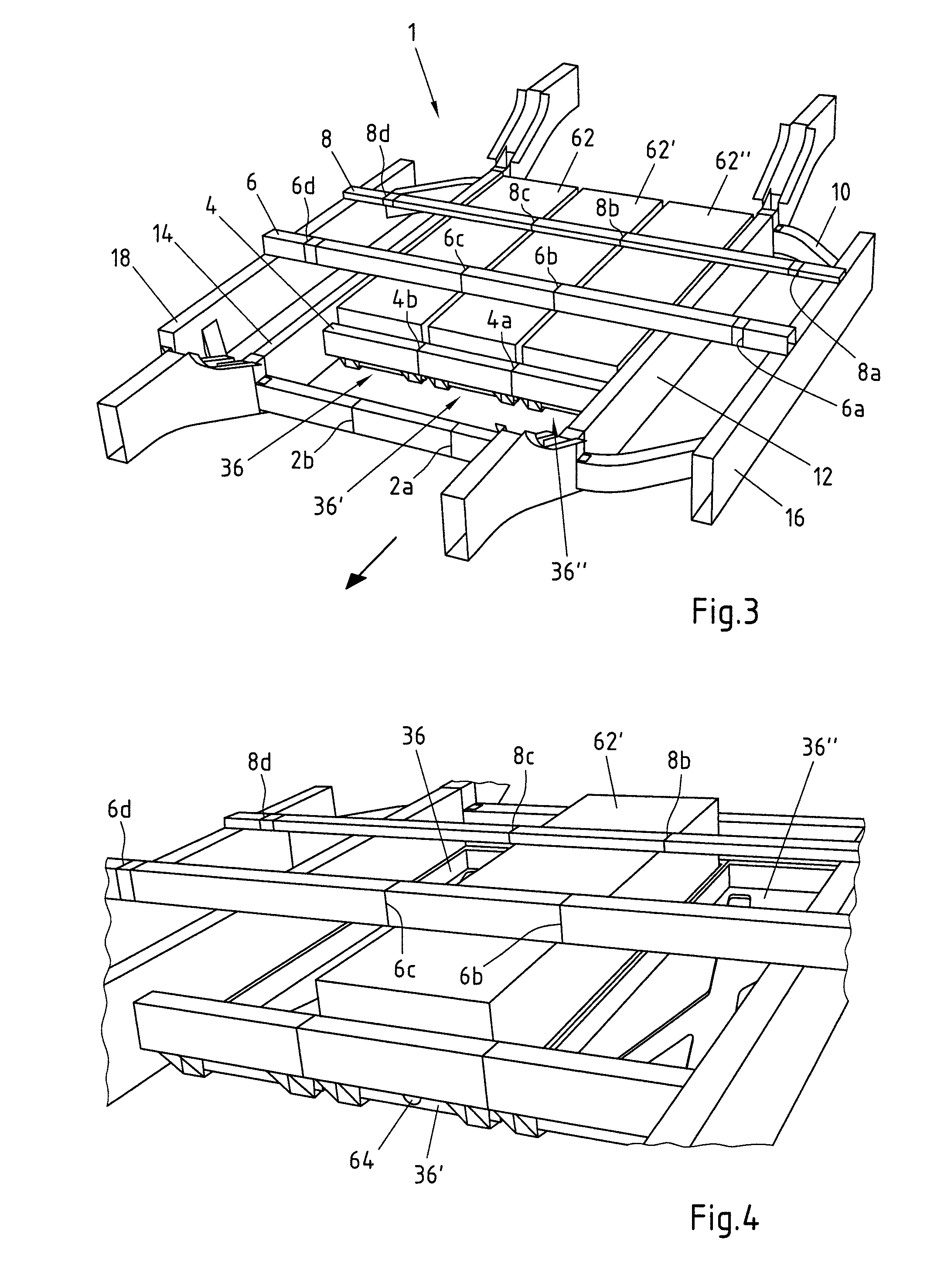
[0057]FIG. 1 shows an embodiment of a floor structure 1 according to the invention for a vehicle without installed energy storage modules 62, 62′, 62″, in a perspective view from above. The direction of travel of the vehicle and the longitudinal direction is indicated by an arrow. The floor structure 1 has five cross members 2, 4, 6, 8, 10 and two longitudinal members 12, 14. The cross member 4 connects the longitudinal members 12, 14 to one another and is arranged between the longitudinal members 12, 14. In this connection the cross member 4 is formed in one piece. The cross members 6, 8 are arranged above the longitudinal members 12, 14 and connect to sills 16, 18 to one another. The sills 16, 18 are arranged parallel to the longitudinal members 12, 14 and provide additional protection against side impacts in the transverses direction. The cross members 6, 8 are also connected to the longitudinal members 12, 14. It is however also conceivable for the cross members 6, 8 to be arran...


PUM


Abstract

The present invention relates to a floor structure for a motor vehicle with accommodating means for at least two energy storage modules, wherein the accommodating means comprise at least two longitudinal members and at least two cross members. In addition the present invention relates to the use of such a floor structure in a vehicle with an electric and/or internal combustion engine. The technical problem of providing a floor structure that in the event of accidents, in particular side impacts, improves the protection of the batteries in floor structures of vehicles without adversely affecting the weight or the costs, is solved in that the accommodating means have at least one deformation zone with defined deformation behaviour between the energy storage modules.

Description

CROSS-REFERENCE TO RELATED PATENT APPLICATIONS[0001]This patent application is a continuation of PCT / EP2012 / 062343, filed Jun. 26, 2012, which claims priority to German Application No. 102011051698.0, filed Jun. 8, 2011, the entire teachings and disclosure of which are incorporated herein by reference thereto.FIELD OF THE INVENTION[0002]The present invention relates to a floor structure for a vehicle with accommodating means for at least two energy storage modules, wherein the accommodating means comprise at least two longitudinal members and at least two cross members. The present invention furthermore relates to the use of such a floor structure in a vehicle with an electric and / or internal combustion engine.BACKGROUND OF THE INVENTION[0003]Floor structures for motor vehicles of the type mentioned in the introduction are know from the prior art. Since the instantaneous average energy density of energy storage modules such as batteries is significantly less than that of conventiona...

Claims


Application Information

Patent Timeline
Patent Type & Authority Applications(United States)
IPC IPC(8): B62D21/15
CPCB62D21/15B60K1/04B60K2001/0438B60K2001/0472B60Y2306/01B62D21/157B62D1/04
Inventor PATBERG, LOTHARKEUTZ, ANDREASBREIDENBACH, ANDREAS
Owner THYSSENKRUPP STEEL EURO AG
Why Eureka
Try Eureka