Optical module

a technology of optical modules and optical components, applied in the field of optical modules, can solve problems such as transmission errors, and achieve the effect of reducing cross-talk noise and small siz

Active Publication Date: 2014-05-01
PANASONIC INTELLECTUAL PROPERTY MANAGEMENT CO LTD
View PDF6 Cites 8 Cited by
  • Summary
  • Abstract
  • Description
  • Claims
  • Application Information

AI Technical Summary

Benefits of technology

[0008]An object of the present invention is to provide an optical module small in size and low in height in which leaked light or the like from a plurality of optical elements on the same substrate is made less likely to affect the adjacent optical elements and a cross-talk noise can be thereby reduced significantly.
[0025]According to the present invention, the lengths of the adjacent first trenches are different from each other, and the optical elements are mounted on the surface of the substrate so as to oppose the mirror sections formed at the tip portions of the first trenches having the above lengths. Accordingly, it is possible to secure a large distance between the adjacent optical elements disposed at different positions in a length direction, e.g., the unaligned adjacent optical elements.
[0026]Consequently, leaked light from the optical element or reflected scattered light from the mirror section or the internal waveguide becomes less likely to enter the mirror section or the internal waveguide of the adjacent optical element, and hence a cross-talk noise becomes less likely to occur. In addition, the internal waveguides are provided in the plurality of the first trenches formed independently of each other and substantially in parallel with each other, and hence the internal waveguides don't interfere with each other due to the partition wall portion between the adjacent first trenches.
[0027]Thus, a plurality of the optical elements are mounted on the substrate so as to be close to each other in a width direction, and the internal waveguides and the mirror sections are formed at a small pitch so as to correspond to an interval of the optical elements. With this, it becomes possible to implement small in size, low in height, and bidirectional or multi-channel transmission. In addition, it is possible to significantly reduce the cross-talk noise by securing the large distance between the adjacent optical elements and preventing the interference between the adjacent internal waveguides.

Problems solved by technology

Such a cross-talk noise causes a transmission error.

Method used


Image

  • Optical module
  • Optical module
  • Optical module

Examples


first embodiment

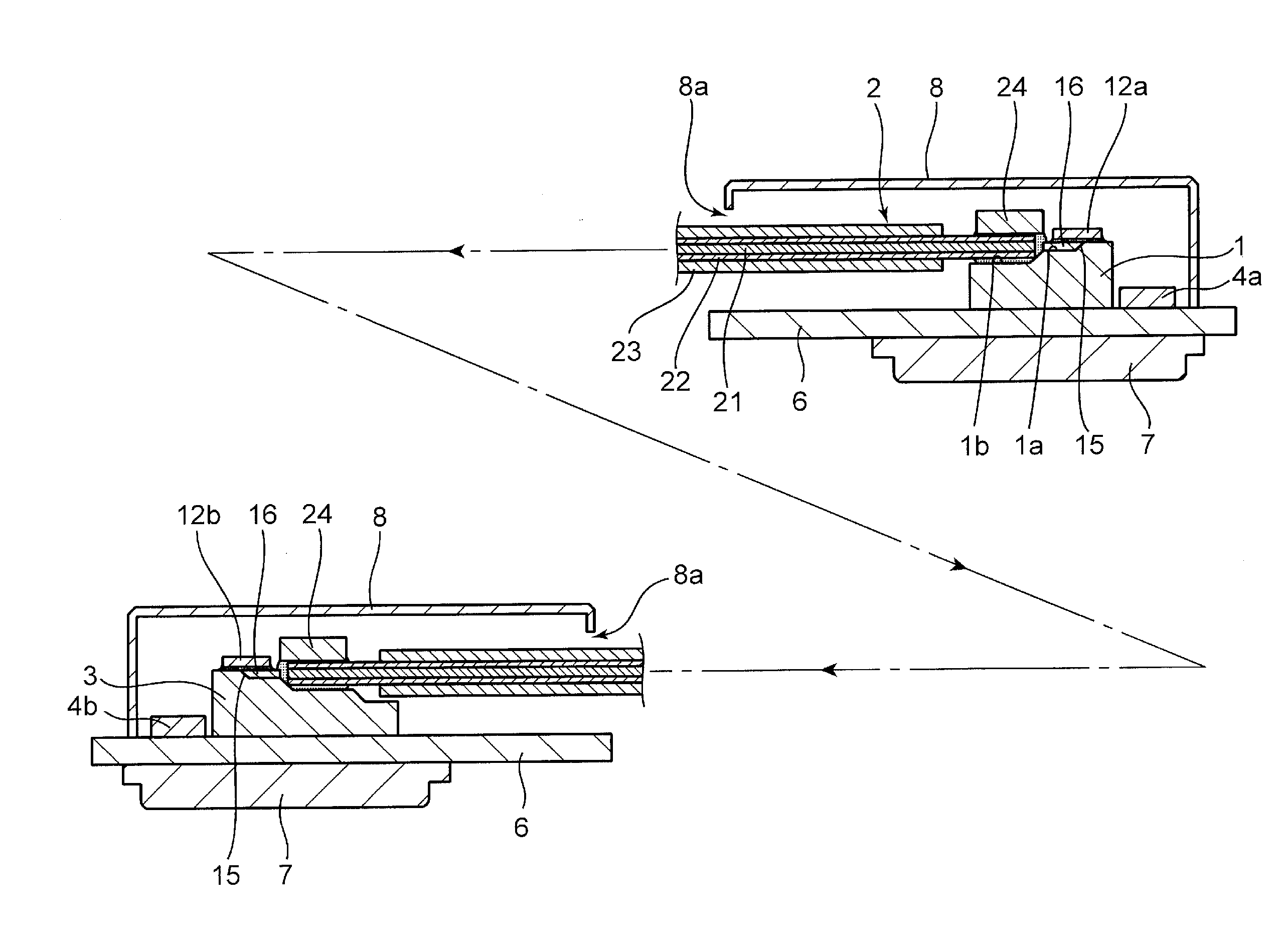
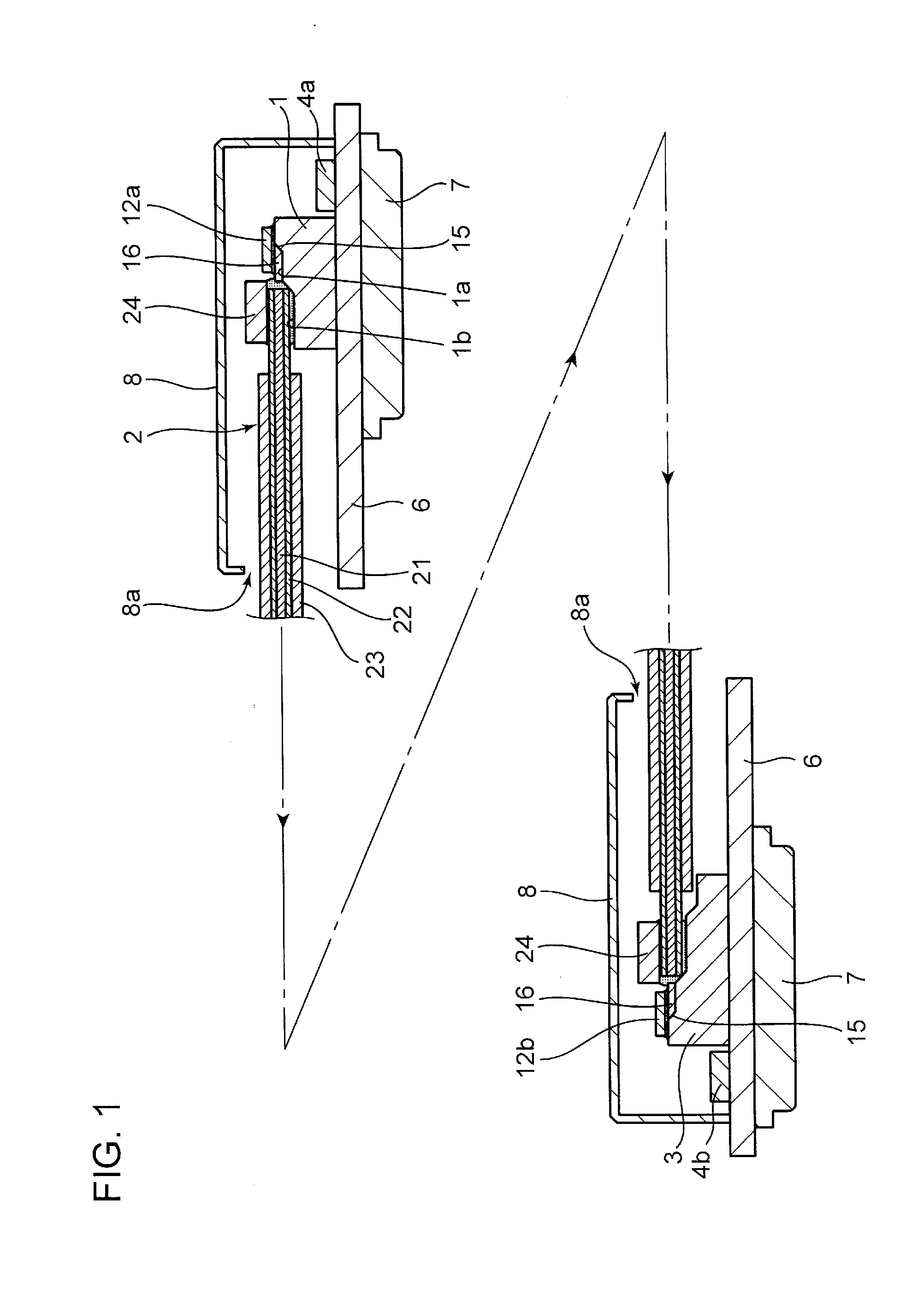
[0057]Each of FIGS. 1 to 5 shows a single channel optical module in which one internal waveguide 16 is formed in one first trench 1a of each of first substrates 1 and 3. The outline of the single channel optical module will be described first with reference to FIGS. 1 to 5 and, thereafter, a detailed description will be given of a multi-channel optical module according to a first embodiment of the present invention that includes the structure of the single channel optical module with reference to FIGS. 6 to 9.

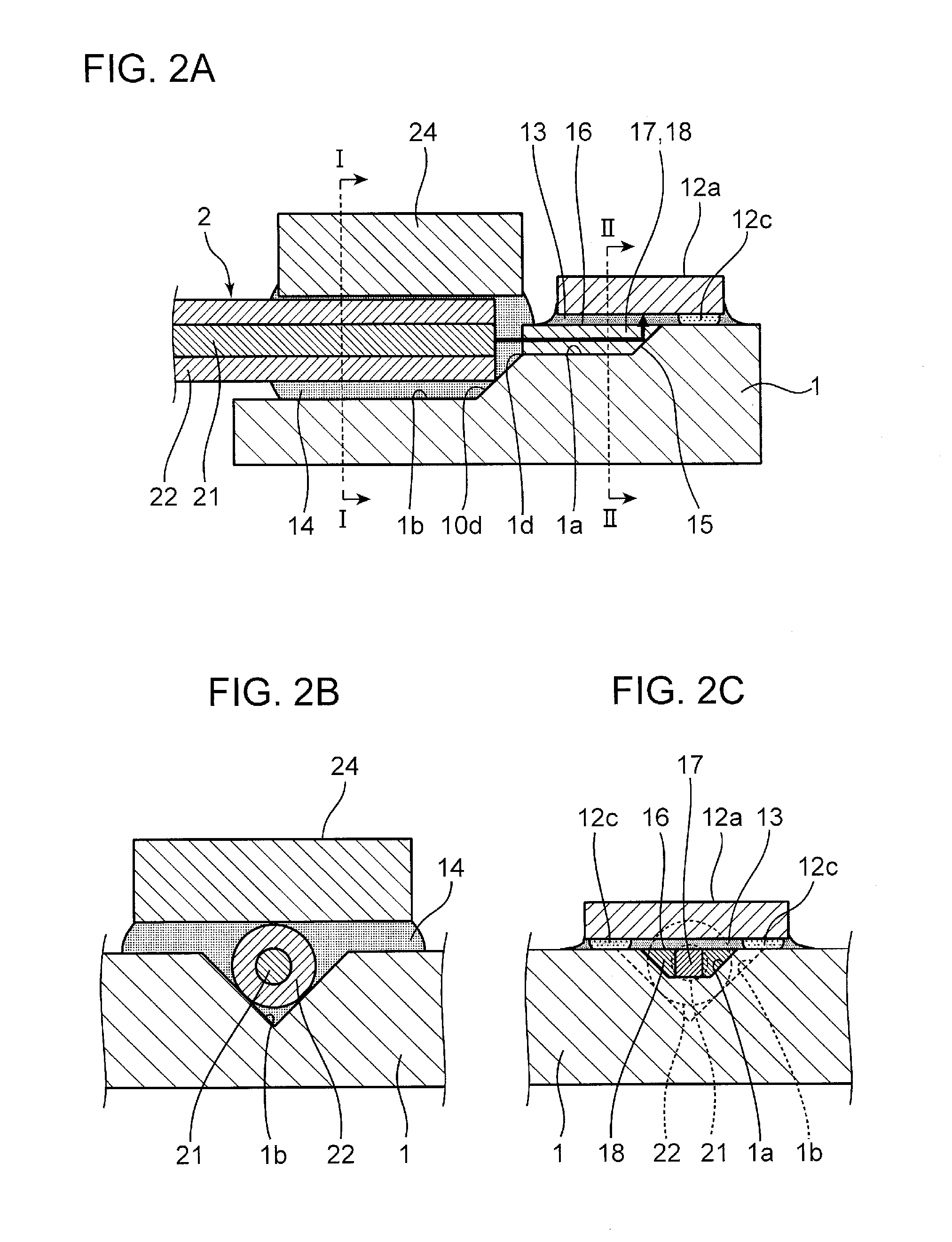
[0058]FIG. 1 is a schematic side view of the single channel optical module. FIGS. 2A to 2C are views showing the first substrate 1 of the optical module on a light-emitting side of FIG. 1, FIG. 2A is a side cross-sectional view of the first substrate 1, FIG. 2B is a I-I line cross-sectional view of FIG. 2A, and FIG. 2C is an II-II line cross-sectional view of FIG. 2A. FIGS. 3A and 3B are views showing the first substrate 1, FIG. 3A is a perspective view of the first substrate 1...

second embodiment

[0140]In the first embodiment, although the example in which the second trench having the V-shaped cross section in which the optical fiber 2 functioning as the external waveguide is fitted is formed is described, the present invention is not limited thereto and, as in a second embodiment shown below, a structure may also be adopted in which the second trench having a trapezoidal cross section, i.e., the second trench in a shape having a bottom surface having a predetermined width and two inclined surfaces on both ends of the bottom surface is provided.

[0141]Herein, in order to describe, in detail, the structure of the optical module of each channel included in the multi-channel optical module (see FIGS. 23A and 23B) according to the second embodiment of the present invention, first, a description will be given by using the single channel optical module in FIGS. 10 to 22 as an example of a simplified structure.

[0142]Note that the configuration of the single channel optical module sh...


PUM


Abstract

There is provided an optical module in which leaked light or the like from a plurality of optical elements on the same substrate is made less likely to affect adjacent optical elements, and a cross-talk noise can be thereby significantly reduced. The optical module includes an internal waveguide in a first trench of a substrate, a mirror section, and optical elements. A plurality of the first trenches of the substrate are formed independently of each other and substantially in parallel with each other, and lengths of adjacent first trenches from the end surface of the substrate are made different from each other. The optical elements are mounted on the surface of the substrate so as to oppose the minor sections formed at the tip portions of the first trenches having the different lengths.

Description

TECHNICAL FIELD[0001]The present invention relates to an optical module including an optical element.BACKGROUND ART[0002]Conventionally, there is known an optical module that includes an internal waveguide, a mirror section for changing an optical path, an optical element, and an external waveguide. The internal waveguide is provided in a trench formed in the surface of a substrate. The mirror section for changing the optical path is formed at the tip portion of the trench. In addition, the optical element is mounted on the surface of the substrate so as to oppose the mirror section. The optical element emits an optical signal to a core section of the internal waveguide via the mirror section, or receives the optical signal from the core section of the internal waveguide via the mirror section. The external waveguide has a core section optically coupled to the core section of the internal waveguide.[0003]In such an optical module, in order to achieve bidirectional transmission or an...

Claims


Application Information

Patent Timeline
Patent Type & Authority Applications(United States)
IPC IPC(8): G02B6/43
CPCG02B6/43G02B6/4214G02B6/423G02B6/3636G02B6/4249H01L2224/73204H01S5/02326H01S5/02251H01S5/026
Inventor MATSUMOTO, TAKUYAASAHI, NOBUYUKIKINUGASA, YUTAKAYAMAJI, TADAHIRONISHIMURA, MAKOTO
Owner PANASONIC INTELLECTUAL PROPERTY MANAGEMENT CO LTD
Why Eureka
Try Eureka