
Orthodontic appliance with snap fitted, non-sliding archwire

a technology of archwires and orthodontic appliances, applied in the field of orthodontic appliances, can solve the problems of requiring too much time to prepare and/or install, requiring manual labor, and requiring a human to perform the process, etc., and achieve the effect of convenient attachment of the bracket to a single tooth

Active Publication Date: 2014-05-01
UNIV OF SOUTHERN CALIFORNIA
View PDF10 Cites 57 Cited by
  • Summary
  • Abstract
  • Description
  • Claims
  • Application Information

AI Technical Summary

Benefits of technology

The patent is about an orthodontic appliance that uses an archwire and multiple brackets to move teeth. Each bracket has a special design that attaches to a single tooth, allowing for a snapping action with the archwire. The male connectors on the archwire cannot slide after they are locked in the bracket. The appliance also has a manual unlocking action to disengage the male connectors from the bracket. This design prevents the bracket from collapsing when the male loop is locked in.

Problems solved by technology

However, each may have drawbacks, such as requiring too much time to prepare and / or install.
However, the pin and tube appliance can present challenges, including:Custom bends and interdental loops may have to be bent manually in the archwire for the pins to fit into the vertical tubes and for the archwire to move the teeth to the desired location.
This process may need to be performed manually by a human and may be very demanding and tedious.The male pin may need to be soldered onto the orthodontic archwire with a needed inclination.
This may also be a very demanding and tedious manual process.The solder joint between the male pin and orthodontic archwire may break.The orthodontic archwire may be difficult to insert and remove from the patient because the locking mechanism may require bending the male insert over the tube to lock and un-bending the male insert from the tube to unlock.Stainless steel wires may be needed.
The may complicate wire bending, pin soldering, and locking, and unlocking procedures when changing wires.The device may be ineffective in dealing with axial rotations of teeth.
However, the edgewise appliance can present problems, including:It may require significant custom wire bending along three axis (or three orders) due to differences in tooth size and tooth position.
This can be time consuming, especially if the brackets are behind the teeth, also known as lingual braces.Sliding the archwire with respect to the orthodontic bracket can require application of external forces.
However, the amount of sliding that can be achieved can be difficult to predict due to the unpredictable nature of the amount of friction to overcome.
However, the pre-adjusted straight-wire appliance can present challenges.
For example, considerable time may be required to tie the archwire into the orthodontic bracket, especially when lingual braces are used.
However, self-ligating orthodontic brackets can present problems, including:Self-ligating orthodontic brackets can sacrifice torque control of the teeth because of a high degree of orthodontic slop that can be present between the orthodontic slot and the archwire.Self-ligating orthodontic brackets may rely heavily on sliding the orthodontic bracket relative to the archwire to open and close space.
This can make control of the teeth much more difficult when using the orthodontic brackets on the lingual surface (behind the teeth) because there may be less interdental space between the orthodontic brackets, resulting in a much more rigid wire that can be harder to control.Self-ligating orthodontic brackets can have several moving parts that can break under wear from occlusal forces in the mouth or from normal use of the appliance.
However, using CAD / CAM technology may not overcome all of the problems associated with the orthodontic appliances, such as:These customized appliances can rely heavily on sliding the orthodontic bracket relative to the archwire to open and close space.
Thus, frequent appointments may still be required to ensure that adequate force is delivered to achieve sufficient tooth movement.Customized orthodontic brackets can also be difficult to tie in, especially when placed on the lingual surface of the teeth.Customized self-ligating orthodontic brackets can be bulky, difficult to control, and damage prone.

Method used


Image

  • Orthodontic appliance with snap fitted, non-sliding archwire
  • Orthodontic appliance with snap fitted, non-sliding archwire
  • Orthodontic appliance with snap fitted, non-sliding archwire

Examples


Embodiment Construction

[0057]Illustrative embodiments are now described. Other embodiments may be used in addition or instead. Details that may be apparent or unnecessary may be omitted to save space or for a more effective presentation. Some embodiments may be practiced with additional components or steps and / or without all of the components or steps that are described.

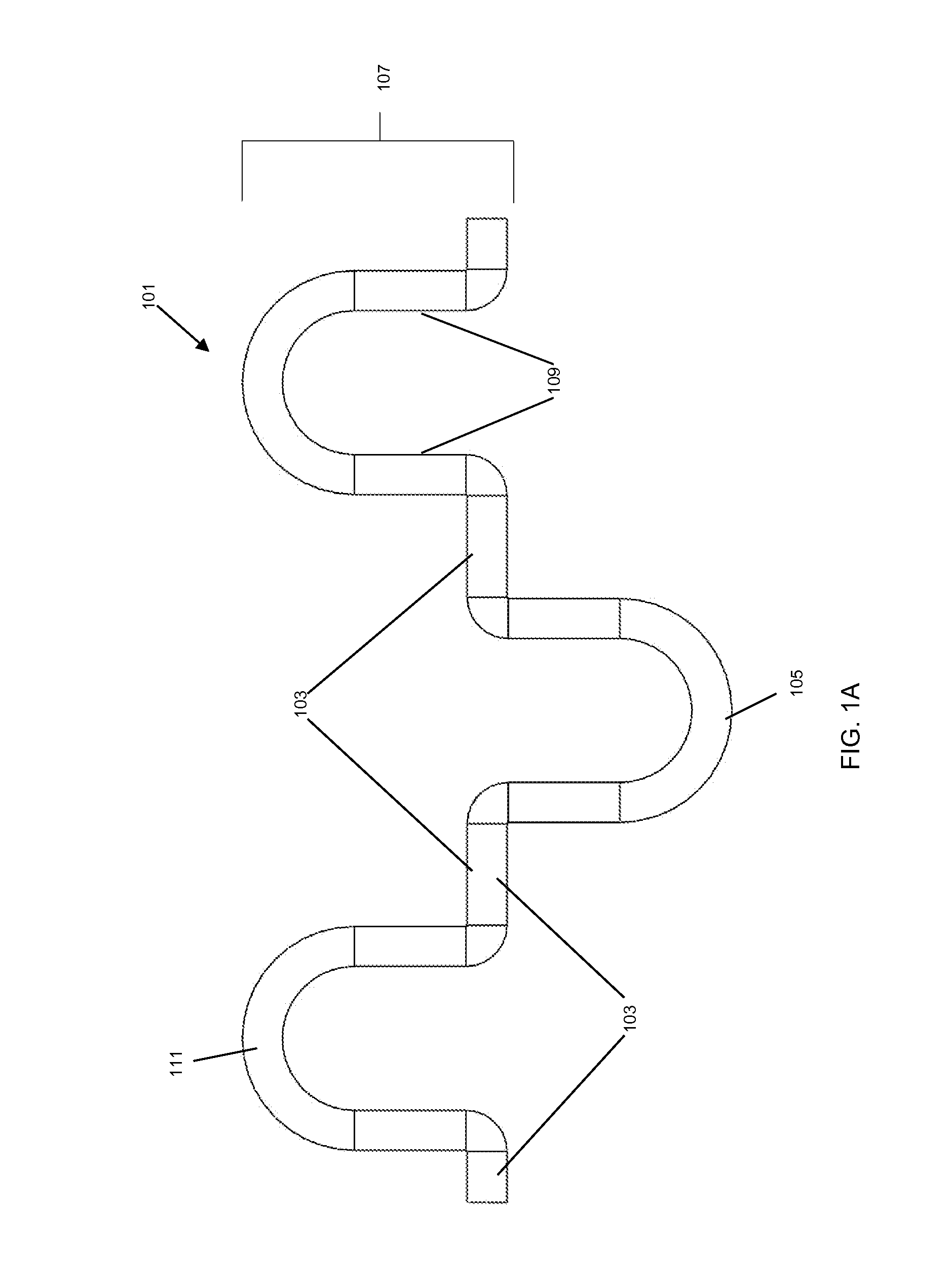
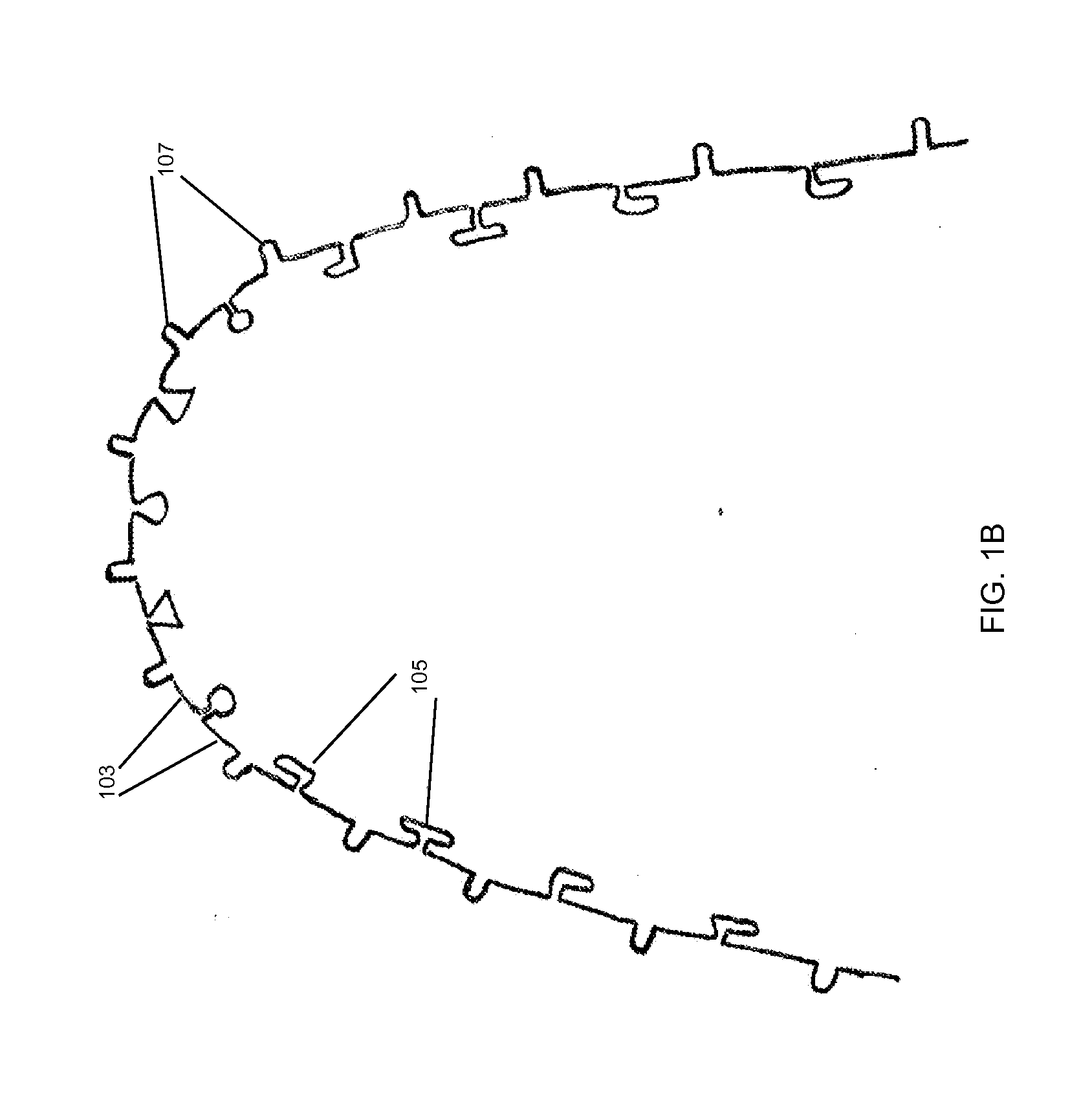
[0058]FIGS. 1A and 1B illustrate an archwire 101 that includes male loops 107 that each include legs 103, sidebars 109, and an arc portion 111. The male loops 107 may be configured to be inserted gingivally and may be separated by interproximal loops 105. The legs 103 may interconnect the male loops 107 and the interproximal loops 105. FIG. 1A illustrates an enlarged two-teeth section of the archwire 101; and FIG. 1B illustrates the entire archwire 101.

[0059]The male loops 107 of the archwire 101 may be configured to snap fit into an orthodontic bracket such that it will not slide with respect to the orthodontic bracket after it has been s...


PUM


Abstract

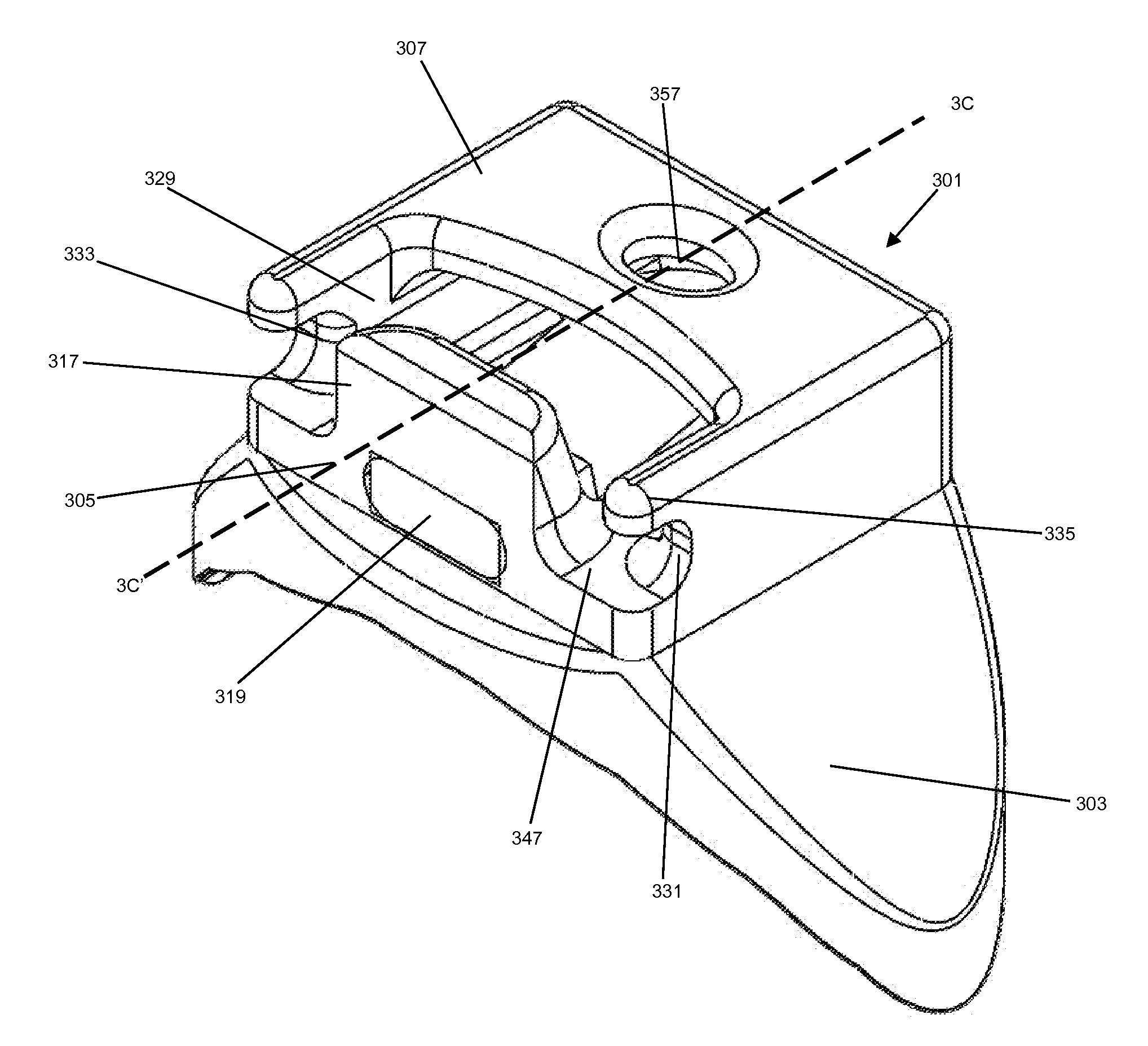
An orthodontic appliance may include an archwire and multiple orthodontic brackets. The archwire may fit within a human mouth and contain multiple male connectors. Each orthodontic bracket may have a configuration that facilitates attaching the orthodontic bracket to a single tooth. Each orthodontic bracket may allow one of the male connectors to be locked into the orthodontic bracket with a snapping action. The male connector may be unable to slide with respect to the orthodontic bracket after being locked in the orthodontic bracket. A manual unlocking action may allow the male connector to disengage from the orthodontic bracket.

Description

CROSS-REFERENCE TO RELATED APPLICATION[0001]This application is based upon and claims priority to U.S. provisional patent application 61 / 720,263, entitled “Frictionless, Self-Activating, Self-Limiting, and Self-Contained,” filed Oct. 30, 2012, attorney docket number 028080-0797. The entire content of this application is incorporated herein by reference.BACKGROUND[0002]1. Technical Field[0003]This disclosure relates to orthodontic appliances, including archwires and associated orthodontic brackets.[0004]2. Description of Related Art[0005]Orthodontic appliances are commonly used to correct misaligned teeth.[0006]There are many types of orthodontic appliances. However, each may have drawbacks, such as requiring too much time to prepare and / or install.[0007]One type of orthodontic appliance is the pin and tube appliance. The pin and tube appliance can control the movement and position of each tooth in three-dimensional space. It can include an orthodontic archwire with a male “pin” that...

Claims


Application Information

Patent Timeline
Patent Type & Authority Applications(United States)
IPC IPC(8): A61C7/30
CPCA61C7/30A61C7/20A61C7/28A61C7/125
Inventor KHOSHNEVIS, BEHROKHTONG, HONGSHENGCHEN, YONGPHAM, PHILONG JOHNLEE, ROBERT
Owner UNIV OF SOUTHERN CALIFORNIA
Learn More